Introduction
For some time now, Industrial Shields® has been using Node-RED as it is a very powerful programming tool for developing all kinds of applications for open source and industrial automation. So we have decided to create Industrial Shields® official nodes of Node-RED for you to use the inputs and outputs in a very easy way.
In this post, we will learn how to use the digital read node for Raspberry Pi PLC.
Related Links
Node-RED tutorial
Requirements
- Raspberry PLC
- Power Supply
- Either Ethernet or HDMI cable with an external screen to connect to your industrial Raspberry Pi PLC.
- Raspberry PLC Industrial Shields C++ Library configuration (Installation 1-7 steps)
- Node-RED-Dashboard Library.
Installation
- Install Node-RED in your Raspberry Pi based PLC, if it is not yet.
- Install the node-red-contrib-rpiplc-node nodes. There are two ways:
- In Node-RED, go to Menu - Manage palette - Install - search for node-red-contrib-rpiplc-node - Install.
- Follow the steps of this link.
Industrial Shields Nodes
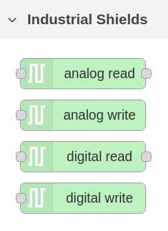
Once the nodes are downloaded, you will be able to see the four nodes in the nodes section, as shown below:

Digital Input Node
In this post, we will focus on the digital read node, which is an input node for reading the Raspberry Pi industrial PLC digital input pins.
So, drag and drop the node to the flow, double-click and add a new Raspberry Pi PLC controller configuration by clicking on the pen.
Then:
- Select the model of the Raspberry PLC.
- Click on Add.
- Select and input.
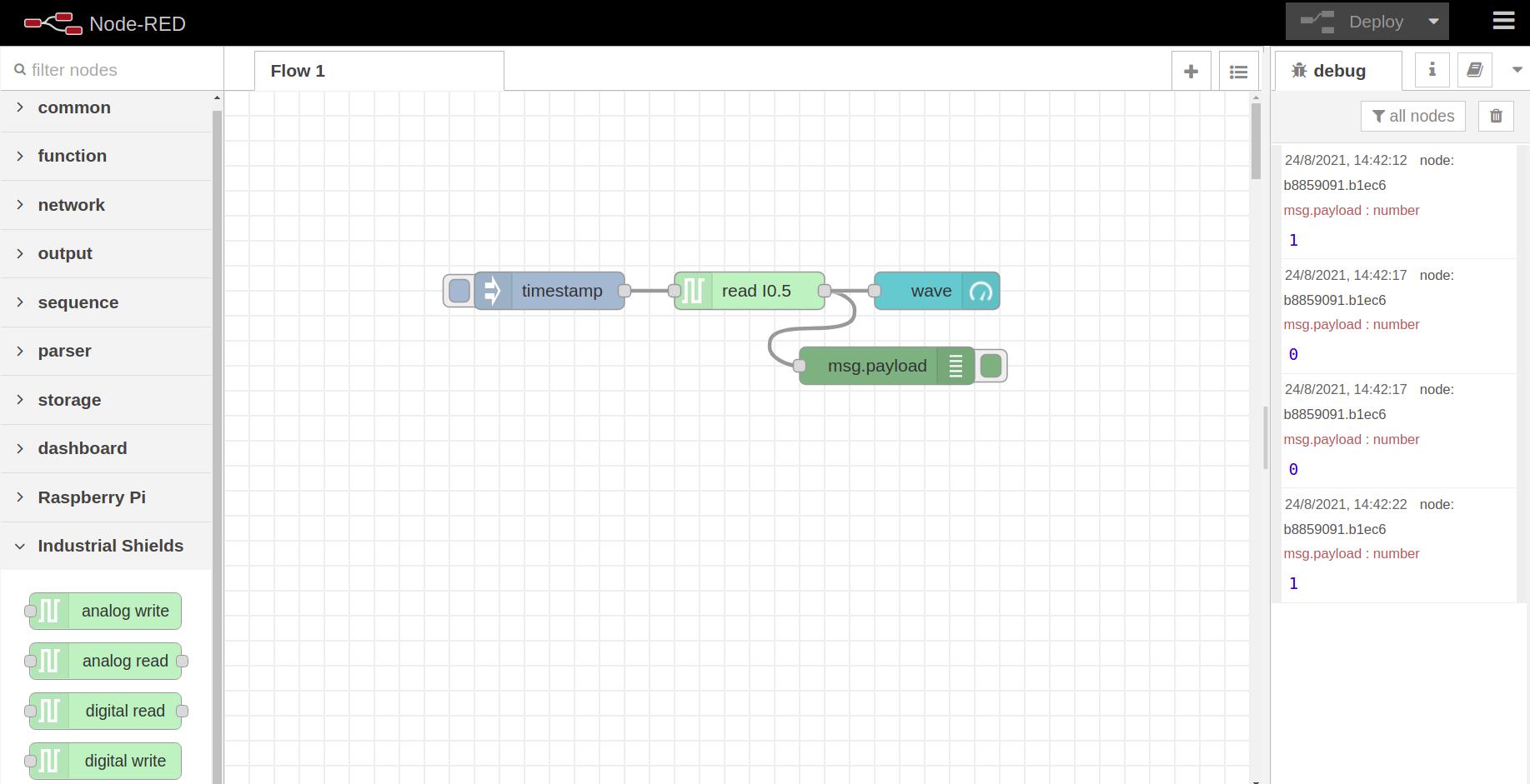
- Wire a debug node after the digital read node to get the value. And an inject node before the node to start getting the value.
- Physically, connect 24V to the I0.5 input to turn on the LED and get a 1 digital value.
- Add an analog-read node, and get the resolution with a debug node.
As we can see in the picture below, this is how we will get the result:

Dashboard
In order to control the data graphically, we are going to add a Dashboard widget and request the temperature every 2 seconds to monitor it with the open source PLC Raspberry Pi.
- In the inject node, select the option: Inject once after 0.1 seconds, then repeat: Interval every 2 seconds.
- Add a gauge node after the digital-read node.
- Add a new ui_group and a new ui_tab.
- Select 6x5 size.
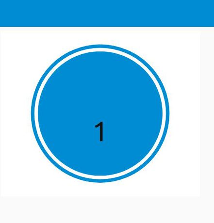
- Select your prefered type, in our case "Level".
- Change the label for the input name
- Set the range between 0 and 1
[{"id":"f5e89d62.2ca78","type":"tab","label":"Flow 1","disabled":false,"info":""},{"id":"ac4ab640.7daf98","type":"rpiplc-digital-read","z":"f5e89d62.2ca78","rpiplc":"9a660914.ca7488","pin":"I0.5","name":"","x":420,"y":160,"wires":[["b8859091.b1ec6","64fac913.dab2f8"]]},{"id":"db0d26d4.246ce8","type":"inject","z":"f5e89d62.2ca78","name":"","props":[{"p":"payload"},{"p":"topic","vt":"str"}],"repeat":"","crontab":"","once":false,"onceDelay":0.1,"topic":"","payload":"","payloadType":"date","x":260,"y":160,"wires":[["ac4ab640.7daf98"]]},{"id":"b8859091.b1ec6","type":"debug","z":"f5e89d62.2ca78","name":"","active":true,"tosidebar":true,"console":false,"tostatus":false,"complete":"false","statusVal":"","statusType":"auto","x":530,"y":220,"wires":[]},{"id":"64fac913.dab2f8","type":"ui_gauge","z":"f5e89d62.2ca78","name":"","group":"33d04b74.74e3e4","order":0,"width":"6","height":"5","gtype":"wave","title":"","label":"","format":"{{value}}","min":0,"max":"1","colors":["#00b500","#e6e600","#ca3838"],"seg1":"","seg2":"","x":570,"y":160,"wires":[]},{"id":"9a660914.ca7488","type":"rpiplc-config","model":"RPIPLC_57R","name":""},{"id":"33d04b74.74e3e4","type":"ui_group","name":"Default","tab":"9882cc2c.3cb1d","order":1,"disp":false,"width":"6","collapse":false},{"id":"9882cc2c.3cb1d","type":"ui_tab","name":"Home","icon":"dashboard","disabled":false,"hidden":false}


Node-RED Tutorial: How to read digital inputs from Raspberry PLC