Getting Started with the Touchberry Panel
The Industrial Shields TouchBerry Pi Panel PC is a Raspberry Pi-based Programmable Logic Controller (PLC) that combines the power of Raspberry Pi technology with the flexibility and robustness needed for industrial automation. Equipped with digital and analog inputs, as well as digital outputs, the Touchberry Panel provides an excellent platform for monitoring and controlling industrial processes with ease.
In this guide, we'll explore how to get started with the Touchberry Panel, covering the essential hardware components required to interface with its inputs and outputs. Whether you're working with digital signals for turning devices on and off, or analog inputs to monitor variables such as temperature or pressure, this blog post will guide you step by step through the process.
The inputs and outputs of the Touchberry Panel include:
- 2 Analog Inputs: Channels I0 and I1
- 3 Digital Inputs: Channels I2, I3, and I4
- 5 Digital Outputs: Channels Q0, Q1, Q2, Q3, and Q4
Additionally, we will dive into various software tools that can be used to interact with the Touchberry Panel, including:
- Bash commands for quick control and troubleshooting.
- Node-RED, a powerful flow-based tool for creating user-friendly interfaces and automating tasks.
Check the Technical Features for further information about the Touchberry Panel.
Essential Hardware for the Touchberry Panel
When setting up your Touchberry Panel, selecting the right hardware and configuring it correctly is crucial for successful operation. Here’s what you need to get started:
Available Models
- TouchBerry Pi Panel PC 7": A compact and versatile option suitable for smaller applications and tighter spaces. Ideal for users who need a more portable solution without compromising on essential features.
- TouchBerry Pi Panel PC 10.1": A larger display panel providing more screen real estate for detailed monitoring and control tasks. Perfect for applications where a bigger interface can enhance usability and visibility.
Micro SD with an Image
The PLC typically comes with a pre-installed image suitable for the Touchberry Panel. For convenience, you can find ready-to-use images available for download here. Simply write the provided image to your micro SD card to get started.
Analog Input Configuration
The Touchberry Panel supports both 0-10V and 4-20mA modes for analog inputs. To switch between these modes, the jumpers located near the analog input connectors (JP1 and JP2) must be accordingly set up:
- For 0-10V Mode: Set both JP1 and JP2 jumpers to the right.
- For 4-20mA Mode: Set both JP1 and JP2 jumpers to the left.
The input and output pins must be powered through the 24V COM and GND COM pins before powering the PLC.
Software Implementations
Once you have your Touchberry Panel set up with the correct hardware, you can start interacting with it through various software methods. Each software approach offers unique advantages for different use cases. Here’s an overview of how to work with the Touchberry Panel using Bash commands and Node-RED.
Bash commands
Using Bash commands is a straightforward way to interact with the Touchberry Panel, especially for quick tests and operations. Below are some essential commands to read and set inputs and outputs. The /home/pi/test directory comes with the provided default image:
Read Analog Input (4-20mA mode)
Replace <input> with the specific analog input channel you want to read, such as I0 or I1.
Read Analog Input (0-10V mode)
Replace <input> with the specific analog input channel you want to read, such as I0 or I1.
Read Digital Input
Replace <input> with the digital input you want to read. Available channels are I2, I3, and I4.
Set Digital Output
Replace <output> with the digital output channel (Q0 to Q4) and <value> with 1 to turn it ON or 0 to turn it OFF.
Node-RED
In this section, we'll explore how to use Node-RED to create a user-friendly dashboard for monitoring and controlling the Touchberry Panel. Node-RED allows you to design flows that can interact with the panel’s inputs and outputs, providing a visual interface for easier management.
Node-RED Flow
To help you get started, you can import the provided Node-RED flow:
Here’s a brief overview of how the flow works:
- Switch Nodes: Each switch on the dashboard is linked to an exec block that runs the corresponding Bash command to set digital outputs.
- Exec Nodes: These nodes execute Bash commands to read digital and analog inputs. For digital inputs, the command is executed every second to keep the dashboard updated.
- Dashboard Nodes: These nodes display the current state of inputs and outputs, providing real-time feedback.
Dashboard Overview
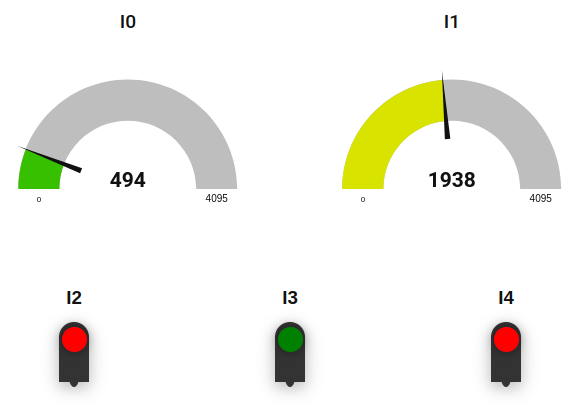
- Inputs Dashboard: This section displays the status of digital and analog inputs.
- Analog Inputs: Analog inputs are shown with gauges or charts that update periodically based on the retrieved data. Depending on the mode (0-10V or 4-20mA), the displayed values will reflect the current measurements from the analog inputs.
- Digital Inputs: Each digital input is represented by a visual element (such as a lamp or a status indicator) that updates in real-time based on the command executed every second. You’ll see whether each digital input is on or off, providing a clear view of the input states.
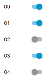
- Outputs Dashboard: This section allows you to control the digital outputs directly from the Node-RED interface.
- Digital Outputs: Each digital output is represented by a switch or button. Clicking or toggling these controls will execute the corresponding Bash command to set the digital output to ON or OFF. This provides an easy way to manage and monitor the state of digital outputs.By using this dashboard, you’ll have a comprehensive and intuitive interface to interact with your Touchberry Panel, making it easier to monitor inputs and control outputs from a single location.