Before starting
Modbus RTU is a widely used protocol to interact with slave devices, to write and read over their registers and control multiple end-points at the time. For a basic introduction to Modbus RTU, check out the following blog posts:
Basic setup
In this example, we used a Touchberry Panel, but the configuration and performance of the UPSafePi is the same, as it used the same GPIOs.
The Touchberry Panel will act as the master, because the screen that incorporates can be very useful to show the current states of all devices connected over Modbus RTU, such as other Industrial Shields PLCs, generic controllers or sensors.
To connect the devices, wire all the A+ pins and all the B- pins using twisted wire pairs to minimize signal reflections. Then, power up the Touchberry Panel and connect a keyboard and a mouse using the USB ports under it.
First of all, open a terminal and install the libgpiod-dev depencendy:
sudo apt install libgpiod-dev
Then, create a folder to store all the files:
mkdir modbusrtu && cd modbusrtu
Then download the corresponding files and store them under the modbusrtu directory.
This two files compose the Modbus RTU library for Touchberry Panel / UPSafePi. The Raspberry Pi port which is used to work over RS-485 is the /dev/ttyAMA0.
OS related configuration
Before starting, ensure you Operative System version is updated to the newest version (Bookworm 12 at the moment of writing this post). You can check your own version with cat /etc/os-release.
Then, add the following line in /boot/firmware/config.txt. You can open this file with:
sudo nano /boot/firmware/config.txt
By default, the Raspberry Pi serial port is /dev/ttyS0, but it is a miniUART and, because of its hardware limitations, lacks parity control, leading to incompatibility with most of Modbus RTU slave devices. The UART that has parity control is automatically occupied by the Bluetooth device.
In order to change that, we use the previous configuration. We specify the Raspberry Pi's Bluetooth device to use this miniUART, so the RPI's serial port can automatically occupy the UART, which has parity control. This serial port in specific is /dev/ttyAMA0.
Finally, reboot the device.
Test code
To test the functionality of the library we can use a script that takes as parameters the next variables:
- Slave ID
- Baudrate
- Serial configuration
- Function Code
- Address
- Value to write / Quantity to read
The code is the following:
#include <stdio.h>
#include <unistd.h>
#include <stdlib.h>

#include "modbus.h"

///////////////////////////////////////////////////////////////////////////////////////
int main(int argc, char* argv[]) {

  if (argc <= 5) {
    printf("Missing parameters\n");
    return 1;
  }

  int slave_id   = atoi(argv[1]);
  int baudrate   = atoi(argv[2]);
  char *serial_c = argv[3];
  int fc         = atoi(argv[4]);
  int address    = atoi(argv[5]);

  uint16_t i_reg[100];
  char d_inp[100];
  char coils[100];
  uint16_t h_reg[100];

  modbus_err_t err;

  // Start modbus
  if (modbus_begin(slave_id, baudrate, getSerialConfig(serial_c))) {
    return 1;
  }

  // Read digital outputs
  if (fc == 0x01) {
    int quantity = atoi(argv[6]);

    err = read_coils(address, quantity, coils);
    if (err != NO_ERR) {
      fprintf(stderr, "Error: %s\n", getErrorCode(err));
      return 1;
    }
    for (int i = 0; i < quantity; i++) {
      printf("%d", coils[i]);
      if (i < quantity - 1) printf(",");
    }
    printf("\n");
    return 0;
  }

  // Read digital inputs
  if (fc == 0x02) {
    int quantity = atoi(argv[6]);

    err = read_discrete_inputs(address, quantity, d_inp);
    if (err != NO_ERR) {
      printf("Error: %s\n", getErrorCode(err));
      return 1;
    }
    for (int i = 0; i < quantity; i++) {
      printf("%d", d_inp[i]);
      if (i < quantity - 1) printf(",");
    }
    printf("\n");
    return 0;
  }

  // Read analog outputs
  if (fc == 0x03) {
    int quantity = atoi(argv[6]);

    err = read_holding_registers(address, quantity, h_reg);
    if (err != NO_ERR) {
      printf("Error: %s\n", getErrorCode(err));
      return 1;
    }
    for (int i = 0; i < quantity; i++) {
      printf("%hu", h_reg[i]);
      if (i < quantity - 1) printf(",");
    }
    printf("\n");
    return 0;
  }

  // Read input registers
  if (fc == 0x04) {
    int quantity = atoi(argv[6]);

    err = read_input_registers(address, quantity, i_reg);
    if (err != NO_ERR) {
      printf("Error: %s\n", getErrorCode(err));
      return 1;
    }
    for (int i = 0; i < quantity; i++) {
      printf("%hu", i_reg[i]);
      if (i < quantity - 1) printf(",");
    }
    printf("\n");
    return 0;
  }

  // Write digital output
  if (fc == 0x05) {
    int value   = atoi(argv[6]);

    err = write_single_coil(address, value);
    if (err != NO_ERR) {
      printf("Error: %s\n", getErrorCode(err));
      return 1;
    }
    return 0;
  }

  // Write analog output
  if (fc == 0x06) {
    int value   = atoi(argv[6]);

    err = write_single_register(address, value);
    if (err != NO_ERR) {
      printf("Error: %s\n", getErrorCode(err));
      return 1;
    }
    return 0;
  }

  // Write digital outputs
  if (fc == 0x0F) {
    int quantity  = atoi(argv[6]);
    if (argc - 7 != quantity) {
      printf("Error: Not enough values for coils, expected %d, got %d\n", \
             quantity, argc - 7);
      return 1;
    }
    for (int i = 0; i < quantity; i++) {
      coils[i] = atoi(argv[i + 7]);
    }

    err = write_multiple_coils(address, coils, quantity);
    if (err != NO_ERR) {
      printf("Error: %s\n", getErrorCode(err));
      return 1;
    } else {
      return 0;
    }
  }

  // Write analog outputs
  if (fc == 0x10) {
    int quantity = atoi(argv[6]);
    if (argc - 7 != 2 * quantity) {
      printf("Error: Not enough values for registers, expected %d, got %d\n", \
             quantity * 2, argc - 7);
      return 1;
    }

    for (int i = 0; i < quantity; i++) {
      h_reg[i] = atoi(argv[i + 7]);
    }

    err = write_multiple_registers(address, h_reg, quantity);
    if (err != NO_ERR) {
      printf("Error: %s\n", getErrorCode(err));
      return 1;
    }
    return 0;
  }

  modbus_close();
}
From what can be seen, the library adapts this Function Codes:
- FC 1: Read Coils.
- FC 2: Read Discrete Inputs.
- FC 3: Read Holding Registers.
- FC 4: Read Input Registers.
- FC 5: Write Single Coil.
- FC 6: Write Single Register.
- FC 15: Write Multiple Coils.
- FC 16: Write Multiple Registers.
To compile the code, use:
gcc -o main main.c modbus.c -lgpiod
And to run:
./main <slave_id> <baudrate> <serial_config> <fc> <address> <value/quantity>
For instance, take a look at the next image:
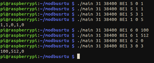
- The first commands are with FC: 5, write coils. This set coils 0, 1 and 3 to 1.
- When reading the coils (FC: 1), it can be seen that they are written correctly.
- Next, FC: 6, which is write registers. We write 100 to register 0, 512 to register 1 and 0 to register 2.
- FC: 3 is read holding registers, and we can clearly see that it works.
This method of setting the parameters in the command line can be very useful when calling the script from a python application or Node-RED, as this script is very flexible and can be called multiple times to interact with more that one slave, changing Slave ID, Baud rate or the function code.
Code alternative
Instead of setting the parameters on the command line, we can create a script to do some petitions sequentially. For example, let's do the same as seen in the image above:
#include <stdio.h>
#include <unistd.h>
#include <stdlib.h>

#include "modbus.h"

#define QUANTITY_COILS 5
#define QUANTITY_REGS  3

///////////////////////////////////////////////////////////////////////////////////////
int main(int argc, char* argv[]) {

  modbus_err_t err;

  // Start modbus
  if (modbus_begin(31, 38400, SERIAL_8E1)) {
    return 1;
  }

  // Write coils
  uint8_t values[QUANTITY_COILS] = {1, 1, 0, 1, 0};
  uint8_t coils[QUANTITY_COILS];

  if (write_multiple_coils(0, values, QUANTITY_COILS) != NO_ERR) {
    return 1;
  }

  // Read coils
  if (read_coils(0, QUANTITY_COILS, coils) != NO_ERR) {
      return 1;
  }
  for (int i = 0; i < QUANTITY_COILS; i++) {
    printf("%d", coils[i]);

    if (i < QUANTITY_COILS - 1) {
      printf(",");
    }
  }
  printf("\n");

  // Write registers
  uint16_t regs[QUANTITY_REGS] = {100, 512, 0};
  uint16_t h_reg[QUANTITY_REGS];

  if (write_multiple_registers(0, regs, QUANTITY_REGS) != NO_ERR) {
    return 1;
  }

  // Read holding registers
  if (read_holding_registers(0, QUANTITY_REGS, h_reg) != NO_ERR) {
    return 1;
  }
  for (int i = 0; i < QUANTITY_REGS; i++) {
    printf("%hu", h_reg[i]);

    if (i < QUANTITY_REGS - 1) {
      printf(",");
    }
  }
  printf("\n");

  modbus_close();
}
Using this code and compiling just like the other (gcc -o main2 main.c modbus.c -lgpiod), we get this result:
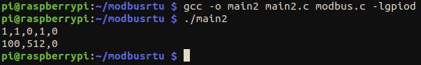
The result is the same, we have successfully written and read accordingly to the test we did previously.
A step further
Thanks to the flexibility of the library, it can be possible to create and develop an User Interface with Node-RED. For instance, take a look at this simple design:

This is only a basic approach. It can be taken as a starting sketch, but should be adapted to the user needs. The sketch flow is attached below. Remember to use the first code seen in this post, and compile it naming the executable file "main" (gcc -o main main.c modbus.c -lgpiod).
flows.json