
In industrial automation, establishing effective communication between devices is essential. This post focuses on the practical aspects of integrating UPSafePi with an M-Duino PLC through the RS485 protocol. We will see the necessary steps, from connecting the hardware to programming, to properly communicate the UPSafePi with an M-Duino using the RS485 protocol, understanding how each device works.
Requirements


Connections
In order to communicate the two devices with RS485, the only necessary connections are:
- A+ (M-Duino) -> A (UPSafePi)
- B- (M-Duino) -> B (UPSafePi)
Also, remember to power both devices with a proper power supply: from 12 to 24 Vdc.
UPSafePI setup
The UPSafePi has 1 RS485 port supporting half-duplex communication. In order to use the RS485 with the UPSafePi, two things need to be taken into account:
- The serial port. Data is sent and received through the serial port of the Raspberry Pi. This port is the "/dev/ttyS0", and needs to be properly configured so we can access it.
- The DE/RE pin (GPIO 27). This pin is used to define the direction of the communication in half-duplex RS485 (in full-duplex they would be 2 separate pins, DE and RE, driver enable and receive enable respectively). In order to send or receive data, this pin needs to be toggled appropriately:
- To transmit, set the pin to HIGH.
- To receive, set the pin to LOW.
OS configuration
Let's start with the configuration of the UPSafePI, as there are a few necessary configurations to use the RS485 communication. Follow these steps to properly setup your UPSafePi:
- The first requirement is to have a correct OS installation. If you do not have Raspberry Pi OS installed already, or want to start from a new one, you can install one to your SD card following this Raspberry tutorial.
- After having a Raspberry Pi OS installation, boot it into your Raspberry Pi and login. The default user has the name "pi" and the password "raspberry".
- Open a terminal (in case you are using a GUI) and type the command sudo raspi-config. Navigate to "Interface" > "Serial Port" using the arrow and the enter key. You will be prompted two questions:
- "Would you like a login shell to be accessible over serial?" Select "No".
- "Would you like the serial port hardware to be enabled?" Select "Yes".
- Exit the raspi-config tool using the escape key.
- In the "/boot/config.txt" after the "[all]" statement, introduce the following line: "enable_uart=1". You can do this by editing the file with your favorite
text editor. For example with nano: sudo nano /boot/config.txt.
After following these steps the RS485 is available for use in the UPSafePI.


Software example
Let's see how to program the UPSafePi to use RS485 with Python. For this test we will use the following libraries:
- Python Serial: This library provides a way to interact with serial ports on your system. In this case it is be used to interact with the "/dev/ttys0" serial port.
- RPi.GPIO: This library is used for General Purpose Input/Output (GPIO) operations on a Raspberry Pi. In this example it will be used to control the DE/RE pin (GPIO 27).
- Time: the sleep function of this library will be used to introduce waiting times in the program.
First of all, the libraries need to be imported this way:
import serial
import RPi.GPIO as GPIO
import time
Using the serial library we need to initialize the serial port, with parameters such as the baudrate. The DE/RE pin also needs to be initialized:
GPIO.setwarnings(False)

# Setup the GPIO pin used as DE/RE
GPIO.setmode(GPIO.BCM)
gpio_pin = 27
GPIO.setup(gpio_pin, GPIO.OUT)

# Set the GPIO pin to low
GPIO.output(gpio_pin, GPIO.LOW)

# Define RS485 parameters
ser = serial.Serial(
    port='/dev/ttyS0',
    baudrate=38400,
    timeout=1
)
After this the read and write functions from the serial library can be used. However, we need to remember to properly toggle the DE/RE pin. A good strategy is to set it always LOW except for when we want to transmit, like it is done in the following functions. Also keep in mind to maintain the DE/RE pin in HIGH state for some time after sending data to make sure it has had enough time to be sent.
def send_data(data):
    GPIO.output(gpio_pin, GPIO.HIGH)
    ser.write(data.encode('utf-8'))
    time.sleep(0.1) # Sleep to wait while data is sent
    GPIO.output(gpio_pin, GPIO.LOW)

def receive_data():
        GPIO.output(gpio_pin, GPIO.LOW)
        data = ser.readline().decode('utf-8')
        if data:
            print(f"Received data: {data.strip()}")
With this parts we can assemble a program that transmits and receives messages to an M-Duino. Check the full program:
import serial
import RPi.GPIO as GPIO
import time
# Function to send data
def send_data(data):
GPIO.output(gpio_pin, GPIO.HIGH)
ser.write(data.encode('utf-8'))
time.sleep(0.1) # Sleep to wait while data is sent
GPIO.output(gpio_pin, GPIO.LOW)
# Function to receive data
def receive_data():
GPIO.output(gpio_pin, GPIO.LOW)
data = ser.readline().decode('utf-8')
if data:
print(f"Received data: {data.strip()}")
if __name__ == "__main__":
GPIO.setwarnings(False)
# Setup the GPIO pin used as DE/RE
GPIO.setmode(GPIO.BCM)
gpio_pin = 27
GPIO.setup(gpio_pin, GPIO.OUT)
# Set the GPIO pin to low
GPIO.output(gpio_pin, GPIO.LOW)
# Define RS485 parameters
ser = serial.Serial(
port='/dev/ttyS0',
baudrate=38400,
timeout=1
)
i = 0
while True:
# Send data
send_data("Message " + str(i) +"\r\n")
i +=1
# Receive data
receive_data()
ser.close()
M-Duino setup
The M-duino features two RS485 ports and support full and half-duplex communication. In this example, however, we are communicating with a UPSafePi using half-duplex communication, so the RS485 DIP switch in the PLC must be set to HD (on). If you want to know more about the DIP switches check the hardware section in the technical features page.
After properly setting the switch, the RS485 library included with our boards package can be used to send and receive data. It is used as the Serial Arduino library. Check the following example, designed to work with the UPSafePI program in this page, which receives messages and sends them again.
Do not forget to properly select your board model in the Arduino IDE.
#include<RS485.h>

int i = 0;
char buffer[256];

void setup() {
  // put your setup code here, to run once:
  Serial.begin(115200);
  RS485.begin(38400, HALFDUPLEX, SERIAL_8N1);
}

void loop() {
  uint8_t i = 0;
  if (RS485.available()) {
    while (RS485.available()) {
      buffer[i] = RS485.read();
      Serial.print(buffer[i++]);
    }
    buffer[i] = '\0';

    delay(1000);
    RS485.write(buffer);
  }
}
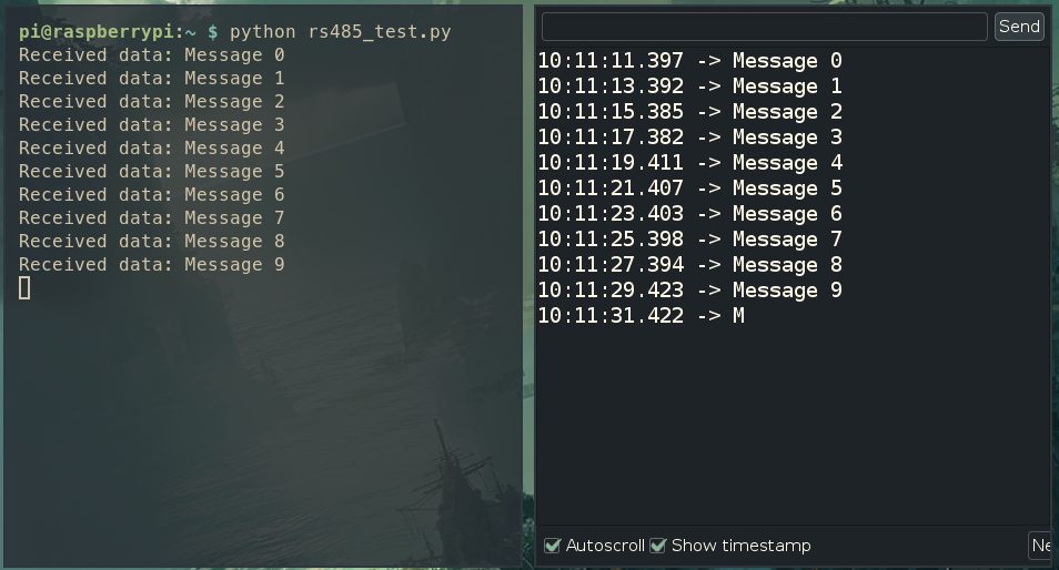
Demonstration
Using the previous program we can interconnect the UPSafePi and the M-Duino. The resulting output from both devices will be the received messages:
Conclusions
In conclusion, successfully communicating between UPSafePi and an M-Duino PLC using RS485 is a fairly simple task, and can be really useful to integrate these devices in various scenarios.
The main difficulty resides in the managing the DE/RE pin, ensuring all data can be properly sent. However, after understanding how it works, RS485 will become a really versatile and practical communication protocol.
How to communicate a UPSafePi with an M-Duino PLC using RS485