
Index
Introduction
In this post, you will learn how to communicate a Raspberry Pi 4 B+ with an M-Duino by RS485 using a MAX 485 module.
Requirements for communicating Raspberry Pi 4 B+ with a MAX485 module
- M-Duino / Ardbox Family
- Touchberry Pi 10.1" w/ UPS & RTC & RS485
- MAX485 module

MAX485 Module
On-board MAX485 chip is a low-power and slew-rate-limited transceiver used for RS485 communication. By adopting half-duplex communication to implement the function of converting TTL level information into RS485 level, it can reach a maximum transmission rate of 2.5 Mbps.
Pinout
Depending on RE and DE connection, the module works as a receiver or transmitter. Connected to VCC, it transmits data and connected to GND it receives data.
It is a cheap module. Batches of 5 units can be found for less than 1€.
Connections
Raspberry Pi to MAX485
| Raspberry Pi 4 B+ Pins | MAX485 Module Pins |
| UART_TXD | RX |
| UART_RXD | TX |
| GPIO 17 | RE |
| GPIO 27 | DE |
MAX485 to M-Duino/Ardbox
| MAX485 Module Pins | M-Duino / Ardbox Pin |
| VCC | 3.3 V |
| B | B- |
| A | A+ |
| GND | GND |
Raspberry Pi 4 B+ Pinout

Diagram

Python Code Example
In this example of code, we send a character from the PLC to the Raspberry Pi. Print it, and answer to the PLC with the same character, which is an "echo". Note that in the case of receiving data, pins 17 and 27 are deactivated and activated in case of transmitting data.
#!/usr/bin/env python3

' IMPORTANT: remember to add "enable_uart=1" line to /boot/config.txt

from gpiozero import OutputDevice
from time import sleep
from serial import Serial

' RO  <-> GPIO15/RXD
' RE  <-> GPIO17
' DE  <-> GPIO27
' DI  <-> GPIO14/TXD

' VCC <-> 3.3V
' B   <-> RS-485 B
' A   <-> RS-485 A
' GND <-> GND

re = OutputDevice(17)
de = OutputDevice(27)

' enable reception mode
de.off()
re.off()

with Serial('/dev/ttyS0', 19200) as s:
	while True:
		' waits for a single character
		rx = s.read(1)

		' print the received character
		print("RX: {0}".format(rx))

		' wait some time before echoing
		sleep(0.1)

		' enable transmission mode
		de.on()
		re.on()

		' echo the received character
		s.write(rx)
		s.flush()

		' disable transmission mode
		de.off()
		re.off()
Take a look at the Programmable Automation Controller based on Raspberry Pi
Automation, monitoring and control with the power and speed of the Raspberry Pi
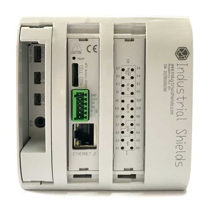
With double RS-485 ports, a double Ethernet port, UPS that will ensure a minimum power supply, this will secure a safe shut down and SD data protection. Also, a CAN bus.
A PLC with the power of Raspberry Pi.
How to communicate Raspberry Pi 4 B+ with a MAX485 module