Complete guide: OpenPLC with industrial PLCs
To use Modbus with OpenPLC on an Arduino Mega, enable Modbus RTU (Serial) in the Communications tab of Transfer Program to PLC, set the baud rate and the slave ID, and give your variables IEC addresses. OpenPLC then serves every %QX output as a coil, every %IX input as a discrete input, every %IW as an input register and every %QW as a holding register. The coil number is 8 times the first index plus the second index, so %QX1.1 is coil 9.
In this guide the Arduino Mega is a Modbus RTU slave over USB. The Ladder program makes two signals that blink in opposite phase, a Modbus master on the PC reads them, and the master stops the whole program by writing one coil. You will build the Ladder diagram, map the variables to coils, upload the program with Modbus enabled and test it with a free master simulator.
The steps and screenshots are from the classic OpenPLC Editor. OpenPLC Editor v4 is a new application with a different interface, so the menus can have other names there. It is the second guide of the series: start with First steps with OpenPLC and Arduino Mega if you have not used OpenPLC yet.
What you need
- An Arduino Mega 2560 and its USB cable.
- The OpenPLC Editor, with the Blink project of the first steps guide.
- A Modbus master on the PC. This guide uses the free Radzio! Modbus Master Simulator for Windows; any Modbus RTU master works.
The same steps work on an M-Duino PLC, which is based on the Arduino Mega, once the Industrial Shields boards are in OpenPLC. See Using ESP32 PLC, M-Duino and Ardbox with OpenPLC.
Build the Ladder diagram
Open the Blink example in File > Tutorials and Examples > 2: Blink. Its TON and TOF timers switch the variable blink_led every 500 ms. Then make three changes:
- In the variables table, add two variables of type
BOOL:blink_led_offandglobal. Set the initial value ofglobalto 1.globalwill stop the whole program. - With the variable tool, place
blink_led_offas an output and connect it to the right of the negatedblink_ledcontact. - With the contact tool, place
globaljust before theblink_ledcoil.
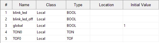
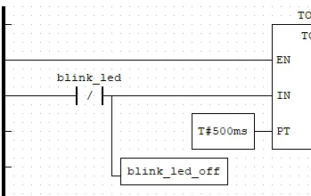
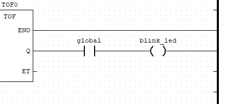
Compile and start the simulation. blink_led_off always takes the opposite value of blink_led. If you set global to 0, both stop.
How OpenPLC maps IEC addresses to Modbus
When Modbus is enabled, OpenPLC adds a Modbus slave to the program it compiles for the board and links each IEC address to a Modbus table. On the Arduino Mega the ranges are these:
| IEC address | Modbus table | Function codes | Arduino Mega range | Master can |
|---|---|---|---|---|
%IX0.0 to %IX2.7 | Discrete inputs | 02 | 0 to 23 | Read |
%QX0.0 to %QX2.7 | Coils | 01, 05, 15 | 0 to 23 | Read and write |
%IW0 to %IW7 | Input registers | 04 | 0 to 7 | Read |
%QW0 to %QW11 | Holding registers | 03, 06, 16 | 0 to 11 | Read and write |
For bits, the Modbus address is 8 times the first index plus the second one: %QX1.1 is 8 × 1 + 1 = 9. For words, it is the index itself: %QW11 is holding register 11. Give the three variables these locations:
| Variable | Location | Coil | Arduino Mega pin with the default I/O Config |
|---|---|---|---|
global | %QX0.7 | 7 | 21 |
blink_led | %QX1.0 | 8 | 23 |
blink_led_off | %QX1.1 | 9 | 25 |
A %QX location is a real output: pins 21, 23 and 25 switch with the variables. Leave them unconnected for this test. With Modbus enabled, every pin in the I/O Config also becomes a coil or a register that the master can write, even if the Ladder program does not use it.
Optional: show the state on the built-in LED
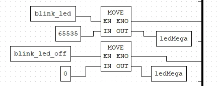
The LED of the Arduino Mega is on PWM pin 13, which OpenPLC maps to the analog output %QW11. Add a variable ledMega of type UINT at %QW11 and two MOVE blocks: 65535 (full scale) when blink_led is on, 0 when blink_led_off is on. The master can also read it as holding register 11.
Enable Modbus RTU and upload the program
Open Transfer Program to PLC, go to the Communications tab and tick Enable Modbus RTU (Serial). This guide uses these values:
| Setting | Value | What it does |
|---|---|---|
| Interface | Serial | The USB serial port of the Arduino Mega |
| Baud | 115200 | Must be the same in the master |
| Slave ID | 1 | The address the master asks for (1 to 247) |
| Tx Pin | -1 | No RS-485 transceiver. With one, it is the pin that enables the transmitter: OpenPLC sets it high while it sends a frame |
| Enable Modbus TCP | Off | The Arduino Mega has no Ethernet or Wi-Fi |
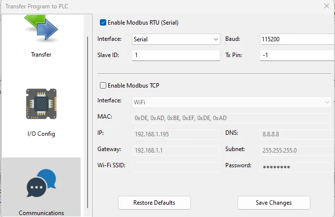
OpenPLC opens the serial port with the default Arduino format: 8 data bits, no parity, 1 stop bit (8N1). Many Modbus devices use even parity by default, so set the master to 8N1 here. Go back to the Transfer tab and upload. If you added the LED, it blinks every half second.
Test the slave with a Modbus master simulator
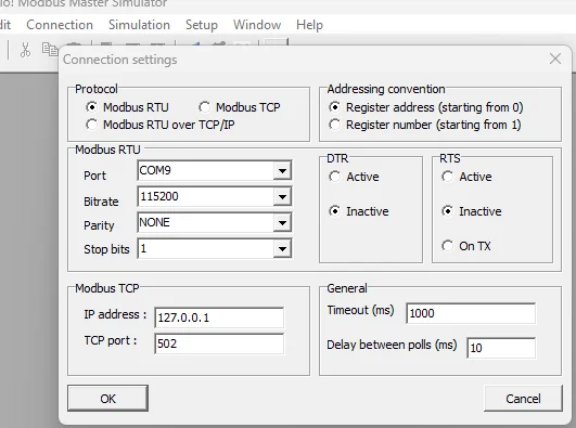
- Open Radzio and go to Connection > Settings. Select Modbus RTU, the COM port of the Arduino, 115200 baud, parity None and 1 stop bit, and "Register address (starting from 0)".
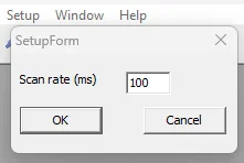
- In Setup > Data definition, set the scan rate to 100 ms.
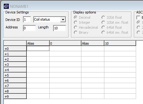
- Create a page with File > New: Device ID 1, Coil status, address 0, length 10.
- Click Connection > Connect. Coils 8 and 9 change every 500 ms and coil 7 stays at 1.
- Double click the value of coil 7 and set it to Off.
globalgoes to 0, coils 8 and 9 stop and the LED turns off.
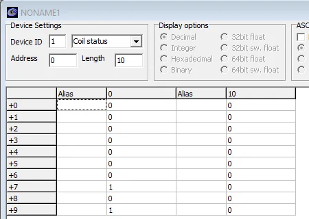
On the wire, the read is the frame 01 01 00 00 00 0A BC 0D (slave 1, function 01, from coil 0, 10 coils, CRC). Writing coil 7 to Off is 01 05 00 07 00 00 7C 0B. The Modbus RTU frame and function codes guide explains each byte.
Disconnect Radzio before you upload a new program. Only one application can use the COM port, and the upload fails while the master holds it.
If the master gets no answer
| What you see | Likely cause | What to do |
|---|---|---|
| Timeout on every request | Wrong COM port, baud rate, parity or slave ID | Use the port of the Arduino, 115200, no parity, 1 stop bit and ID 1 |
| The upload fails in OpenPLC | The master still has the COM port open | Disconnect the master, upload, connect again |
| Values appear one position off | The master numbers coils from 1 | Select addresses from 0, or add 1 (coil 7 is 00008 in 1 based numbering) |
| A coil goes back to its value after you write it | The Ladder program writes that variable on every scan | Write only variables the program does not drive, such as global |
| Coils 8 and 9 never change | global is 0 | Set its initial value to 1, or write coil 7 to On |
From the Arduino Mega to an industrial Modbus network
A Modbus slave over USB is good for learning. In a panel, the slave sits on an RS-485 bus or on Ethernet. An M-Duino PLC keeps the Arduino Mega base and adds RS-485, Ethernet and 24 V inputs and outputs, and the Industrial Shields mod adds it to OpenPLC. If the PLC has to be the Modbus master, program it in the Arduino IDE with the Industrial Shields library, as in Modbus RTU with Arduino and ESP32 based PLCs. To compare the families, read how to choose an industrial controller.
See a full Modbus network before you build one. In the Modbus network simulator, an M-Duino 21 polls four Modbus RTU slaves on RS-485 and serves the data on Modbus TCP. Switch a slave off or change the baud rate and watch the frames.
Open the Modbus network simulatorRead the Modbus temperature network case
FAQ about Modbus in OpenPLC on Arduino
Can an Arduino with OpenPLC be a Modbus master?
The firmware that the OpenPLC Editor builds for Arduino boards includes a Modbus slave only. To poll meters, drives or other PLCs, program the PLC in the Arduino IDE with a Modbus master library.
Why parity None if Modbus RTU uses even parity by default?
OpenPLC opens the Arduino serial port in 8N1. The master and every device on the line must use the same format, so set the master to no parity and 1 stop bit.
Does it work over RS-485?
Yes, with an RS-485 transceiver on a serial port of the board. Set Tx Pin to the pin that enables the transmitter of the transceiver. OpenPLC drives it high while it answers and low after.
How do I read analog values over Modbus?
Analog inputs (%IW) are input registers, read with function 04. Analog outputs (%QW) are holding registers, read with function 03 and written with 06 or 16. OpenPLC uses 0 to 65535: on the Arduino Mega, an analog input is the 10 bit reading multiplied by 64.
Why does the Arduino restart when the master connects?
The Arduino Mega resets when a program opens its USB port with DTR active. Leave DTR inactive in the master, as in the Radzio settings above.