
Complete guide: Choosing an industrial controller
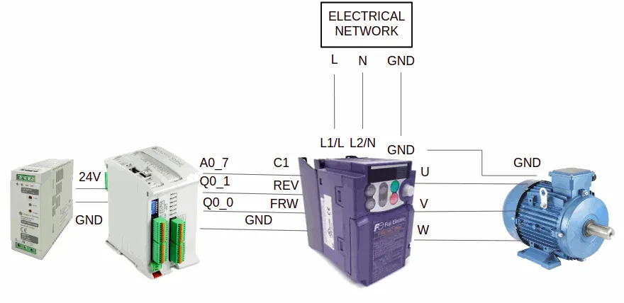
An Arduino based PLC controls a variable frequency drive (VFD) in one of two ways: with hard-wired signals or over a fieldbus. With hard-wired signals, a 0-10 V analog output of the PLC gives the speed setpoint to the voltage input of the drive, and two digital outputs give the run forward and run reverse commands. On an M-Duino 21+, the analog output A0_7 sets the speed (8-bit, analogWrite() from 0 to 255 for 0 to 10 V), and Q0_0 and Q0_1 drive the FWD and REV inputs of the drive. The drive must be set to take its run command from the terminals and its frequency from the voltage input. To read the real speed, the current or the fault codes as well, use Modbus RTU over RS-485.
This guide shows the wiring and an Arduino sketch to start, stop, reverse and change the speed of a three-phase motor from the serial monitor. The test used a Fuji FRENIC-Multi drive (FRN0.75E1S-7E, 0.75 kW, single-phase 200 V supply) and an M-Duino 21+.
What you need
| Part | Used in this guide | What matters |
|---|---|---|
| PLC | M-Duino 21+ | 3 analog/PWM outputs 0-10 V (8-bit) and 5 optoisolated digital outputs, 5 to 24 Vdc |
| Drive | Fuji FRENIC-Multi FRN0.75E1S-7E | A 0-10 V voltage input for the frequency and FWD/REV run inputs |
| Motor | Three-phase induction motor | Rated voltage and power that match the output of the drive |
| Power supply | 24 Vdc | Supplies the PLC and its digital outputs |
How to wire the PLC to the drive
| PLC | Drive terminal (FRENIC-Multi) | Function |
|---|---|---|
| A0_7 (0-10 V) | [12] voltage input | Speed setpoint |
| GND | [11] analog common | Reference of the setpoint |
| Q0_0 | [FWD] | Run forward |
| Q0_1 | [REV] | Run reverse |
| GND (COM-) | [CM] | Common of the digital inputs |
| - | L1/L, L2/N and PE | Mains supply of the drive |
| - | U, V, W and PE | Motor |
- Power the digital outputs. The Q0.x outputs of the M-Duino take their voltage from the output supply terminals, so wire 24 Vdc and COM(-) of the output group.
- Source mode on the drive. An active output of the M-Duino gives 24 V, so the digital inputs of the drive must work in SOURCE mode. On the FRENIC-Multi this is switch SW1; the Fuji manual gives SOURCE as the factory setting of the EU models.
- Voltage input, not current input. On the FRENIC-Multi, terminal [C1] is a 4-20 mA current input by default, and the manual warns not to apply 7.5 V or more to it in that mode. Connect the 0-10 V setpoint to [12], or set [C1] to its voltage function (V2) with the switches and function codes that the manual describes.
How to set up the drive
Two settings tell the drive where its commands come from. On the FRENIC-Multi they are the function codes F01 (frequency command) and F02 (operation method):
- Frequency command: the voltage input [12].
- Run command: the external signals on [FWD] and [REV].
Check the value of each option, the maximum frequency and the acceleration and deceleration times in the manual of your drive. When the drive is set so that 10 V gives the maximum frequency, each of the 255 steps of the 8-bit output is 1/255 of it: about 0.2 Hz with a maximum of 50 Hz.
Arduino sketch: speed and direction from the serial monitor
Select the M-Duino 21+ in the Arduino IDE with the Industrial Shields boards. Open the serial monitor at 9600 baud and send a number: 0 stops, 1 runs forward, 2 runs reverse, and 3, 4 and 5 set 20, 50 and 100 % of the maximum frequency.
// Speed and direction of a variable frequency drive (VFD) from an M-Duino 21+
// A0_7 -> voltage input [12] of the drive (0-10 V speed setpoint)
// Q0_0 -> FWD input, Q0_1 -> REV input
// Commands from the serial monitor: 0 stop, 1 forward, 2 reverse, 3/4/5 speed 20/50/100 %

const uint8_t SPEED_OUT = A0_7;
const uint8_t FWD_OUT = Q0_0;
const uint8_t REV_OUT = Q0_1;

int speedPercent = 20;   // speed setpoint in % of the maximum frequency of the drive
char direction = 'S';    // S = stop, F = forward, R = reverse

void applyOutputs() {
  // Never switch FWD and REV on at the same time
  digitalWrite(FWD_OUT, LOW);
  digitalWrite(REV_OUT, LOW);
  if (direction == 'F') digitalWrite(FWD_OUT, HIGH);
  if (direction == 'R') digitalWrite(REV_OUT, HIGH);

  // 8-bit analog output: 0 = 0 V, 255 = 10 V
  int value = (direction == 'S') ? 0 : map(speedPercent, 0, 100, 0, 255);
  analogWrite(SPEED_OUT, value);

  Serial.print("Direction: ");
  Serial.print(direction);
  Serial.print("  speed: ");
  Serial.print(speedPercent);
  Serial.print(" %  analog value: ");
  Serial.println(value);
}

void printMenu() {
  Serial.println("0 = stop, 1 = forward, 2 = reverse");
  Serial.println("3 = 20 %, 4 = 50 %, 5 = 100 % of the maximum frequency");
}

void setup() {
  Serial.begin(9600);
  pinMode(FWD_OUT, OUTPUT);
  pinMode(REV_OUT, OUTPUT);
  pinMode(SPEED_OUT, OUTPUT);
  applyOutputs();
  printMenu();
}

void loop() {
  if (Serial.available()) {
    char c = Serial.read();
    switch (c) {
      case '0': direction = 'S'; break;
      case '1': direction = 'F'; break;
      case '2': direction = 'R'; break;
      case '3': speedPercent = 20; break;
      case '4': speedPercent = 50; break;
      case '5': speedPercent = 100; break;
      default: return;   // ignore line endings and other characters
    }
    applyOutputs();
  }
}
The sketch never switches FWD and REV on at the same time, and it sets the setpoint to 0 V when the motor is stopped. The drive applies its own acceleration and deceleration ramps, so a change of direction decelerates the motor before it turns the other way.
The sketch compiles and links for the M-Duino 21+ with the Industrial Shields AVR boards package 1.2.1 (6046 bytes). It has not been tested with a drive for this post. Before you run a motor, check the wiring and the drive settings, and keep the emergency stop of the machine on a hard-wired safety circuit.
Analog signals or Modbus RTU?
| Item | 0-10 V and digital signals | Modbus RTU over RS-485 |
|---|---|---|
| Wiring | One cable per signal | One twisted pair for several drives |
| Setpoint resolution | 8-bit output on the M-Duino 21+ | The resolution of the drive register |
| Feedback | Only with extra analog or digital outputs of the drive | Real speed, current and fault codes in registers |
| Setup | Two function codes in the drive | Address, baud rate and register map of the drive |
The PLC Solution Library has a Modbus RTU example that controls two drives from an M-Duino, with run and stop, an RPM setpoint and the real speed read back.
FAQ about VFD control with an Arduino based PLC
Can a PLC output 0-10 V control the speed of any VFD?
Most drives have a 0-10 V voltage input for the frequency setpoint. Check the terminal and the setting in the manual of your drive: some inputs are current inputs (4-20 mA) by default.
Why does the motor not start when the FWD output is on?
Usually the drive still takes its run command from the keypad, or its inputs are in SINK mode while the PLC output gives 24 V. Check the operation method setting and the SINK/SOURCE switch.
What happens if FWD and REV are on at the same time?
On most drives the motor stops or does not start. The sketch avoids this state in software.
Can one PLC control several drives?
Yes. With analog signals each drive needs its own outputs. With Modbus RTU, several drives share one RS-485 bus, each one with its own address.
Can I program the drive control in ladder logic?
Yes, with an IEC 61131-3 environment. See the OpenPLC guide for industrial PLCs.
More about motor control with PLCs
- Controlling a stepper motor with an ESP32 PLC
- Choosing an industrial controller
- Industrial applications: 50 real examples by sector
- Modbus TCP and RTU guide for Raspberry Pi PLCs
See all the Arduino based PLCs.
Take it further
Frequency drives with a PLC in practice: a belt speed loop in a real case and Modbus RTU control of two drives in code.
Case study
The PLC sets the speed. The inverter moves the belt.
An M-Duino 42+ runs the speed loop with analog signals for speed and current, and a Panel PC gives the operator functions.
Read the case study
PLC Solution Library
Variable frequency drive RPM control over Modbus RTU
Run and stop on one register, an RPM setpoint on another and the real speed read back, with two drives on the same RS485 bus.
See the example