
Modbus RTU is the serial version of the Modbus protocol. A master sends a binary frame (slave address, function code, data and a CRC-16) over RS-485 or RS-232, and only the slave with that address answers. Each frame is separated from the next by a silence of at least 3.5 characters.
This reference explains how Modbus RTU works, the frame structure, the data model, the request and response bytes of the eight most used function codes, the exception codes and how to build a frame and its CRC by hand. At the end you will find how the Industrial Shields Modbus RTU master library sends the same frames from an Arduino or ESP32 based PLC. For the full wiring and sketches, go to Modbus RTU with Arduino and ESP32 based PLCs.
What is Modbus RTU?
Modbus is a request and response protocol that Modicon published in 1979 for its PLCs. Today the Modbus Organization maintains the specification, which is public and free to use. Modbus defines the messages (the application layer). Modbus RTU adds the rules to send them over a serial line: binary encoding, a slave address and a CRC check.
- It was designed for industrial control: a PLC reads and writes the registers of other devices.
- It is open and simple to implement, so almost every meter, drive, transmitter and HMI supports it.
- Every frame carries a CRC, so the receiver can detect transmission errors.
- The basic commands read the value of a register or bit, or change it.
Master, slaves and addresses on a Modbus RTU bus
Modbus RTU is the most common Modbus implementation on serial lines. It sends the data in compact binary form, and silences on the line separate one frame from the next.
On an RS-485 bus all the devices share one twisted pair. Only the node configured as master starts a transaction. All the other devices are slaves: they answer requests and never talk on their own. Each slave has a unique address from 1 to 247. Address 0 is a broadcast: every slave executes a write sent to address 0, and none of them answers.
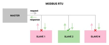
Every slave receives every request, but only the addressed slave acts on it and answers. RS-485 allows 32 unit loads on one segment without a repeater, so a typical bus has one master and up to 31 standard slaves. Transceivers with 1/4 or 1/8 unit load allow more, up to the 247 addresses of Modbus.
We will build one frame along this guide. The master wants the value of 6 input registers of slave 2. The frame starts with the slave address: 02.
Modbus RTU frame structure
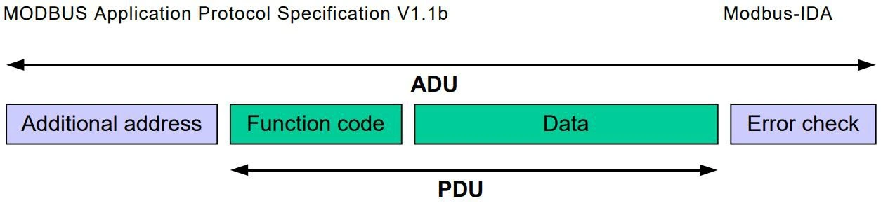
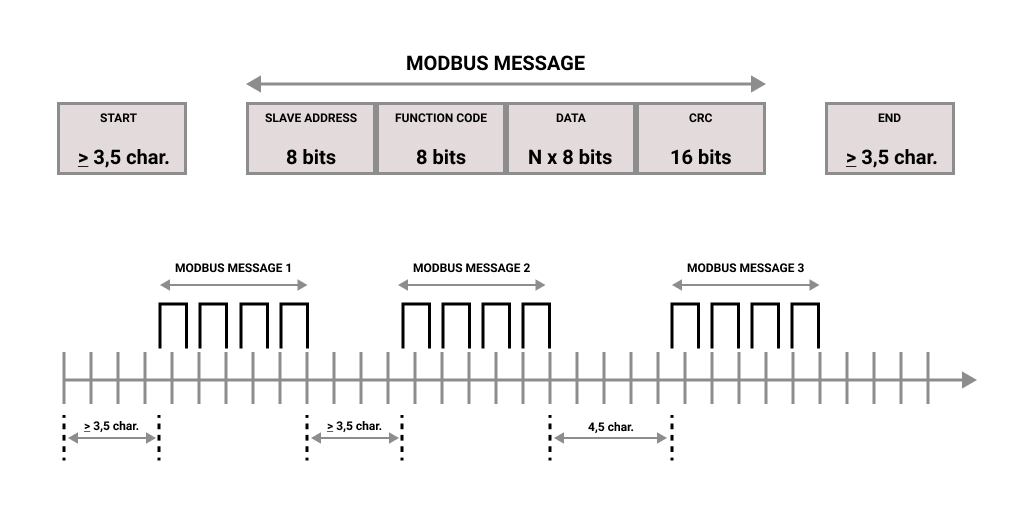
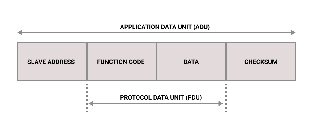
The Modbus RTU Application Data Unit (ADU) has four fields. The function code and the data form the Protocol Data Unit (PDU), which is the same in Modbus TCP.
| Field | Size | Content |
|---|---|---|
| Slave address | 1 byte | 1 to 247 (0 = broadcast) |
| Function code | 1 byte | What the slave must do (1 to 127) |
| Data | 0 to 252 bytes | Addresses, quantities and values. Depends on the function code |
| CRC | 2 bytes | CRC-16/MODBUS, low byte first |
A Modbus RTU frame is 256 bytes at most. Inside a frame, the silence between two characters must not exceed 1.5 character times. Between frames there must be at least 3.5 character times: about 4 ms at 9600 baud and 2 ms at 19200 baud. Above 19200 baud the specification fixes these silences at 750 µs and 1.75 ms.
Modbus function codes
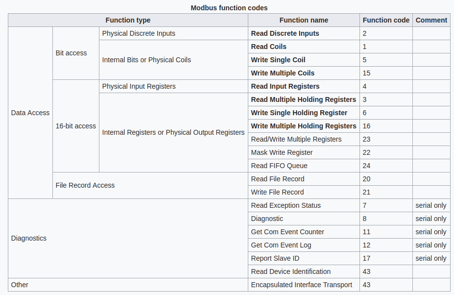
The function code is one byte. Codes 1 to 127 are requests, and the slave answers an error by adding 0x80 to the function code (128 to 255). Code 0 is not valid. These are the function codes that PLCs use every day:
| Code (dec) | Code (hex) | Name | Data table |
|---|---|---|---|
| 01 | 0x01 | Read coils | Coils |
| 02 | 0x02 | Read discrete inputs | Discrete inputs |
| 03 | 0x03 | Read holding registers | Holding registers |
| 04 | 0x04 | Read input registers | Input registers |
| 05 | 0x05 | Write single coil | Coils |
| 06 | 0x06 | Write single register | Holding registers |
| 15 | 0x0F | Write multiple coils | Coils |
| 16 | 0x10 | Write multiple registers | Holding registers |
The specification defines more codes, such as 08 (diagnostics), 23 (read and write multiple registers) and 43 (read device identification), but many devices do not support them.
Exception responses
When a slave cannot execute a request, it answers with the function code plus 0x80 and one exception code. For example, 01 83 02 C0 F1 means that slave 1 rejected a function 03 request because the address does not exist.
| Exception code | Name | Usual cause |
|---|---|---|
| 01 | Illegal function | The slave does not support this function code |
| 02 | Illegal data address | The register or bit does not exist, or the quantity goes past the end of the map |
| 03 | Illegal data value | Wrong quantity or a value out of range |
| 04 | Server device failure | The slave had an internal error while executing the request |
| 06 | Server device busy | The slave is processing a long command. Retry later |
If the slave does not answer at all (wrong address, bad CRC, wrong baud rate), there is no exception code: the master only sees a timeout.
Modbus data model: coils, discrete inputs and registers
Modbus organizes the data of a slave in four tables. Bits can be ON (1) or OFF (0). Registers are 16-bit words.
| Table | Type | Access | Function codes | Usual numbering |
|---|---|---|---|---|
| Coils | 1 bit | Read and write | 01, 05, 15 | 00001 to 09999 |
| Discrete inputs | 1 bit | Read only | 02 | 10001 to 19999 |
| Input registers | 16-bit word | Read only | 04 | 30001 to 39999 |
| Holding registers | 16-bit word | Read and write | 03, 06, 16 | 40001 to 49999 |
The numbers 0xxxx, 1xxxx, 3xxxx and 4xxxx come from device manuals, not from the frame. In the frame each table starts at address 0, so register 40001 is address 0 and register 40108 is address 107.
A register holds 0 to 65535 as an unsigned value, or -32768 to 32767 when the device uses it as a signed integer (two's complement). Values that need more than 16 bits, such as 32-bit counters or floats, use two consecutive registers. The order of the two words depends on the device, so check its manual.
Request and response format of each function code
Every Modbus request and response is an ADU that contains a PDU. The tables below show the PDU: in Modbus RTU, add the slave address before it and the CRC after it. The examples come from the Modbus Application Protocol specification, with the full frame for slave 1 and its CRC.
(0x01) Read coils
Reads from 1 to 2000 contiguous coils of a slave. The answer packs one coil per bit: the least significant bit of the first data byte is the first coil requested. If the quantity is not a multiple of 8, the last byte is padded with zeros.
Request PDU
| Field | Size | Value |
|---|---|---|
| Function code | 1 byte | 0x01 |
| Starting address | 2 bytes | 0x0000 to 0xFFFF |
| Quantity of coils | 2 bytes | 1 to 2000 (0x0001 to 0x07D0) |
Response PDU
| Field | Size | Value |
|---|---|---|
| Function code | 1 byte | 0x01 |
| Byte count | 1 byte | N (quantity / 8, rounded up) |
| Coil status | N bytes | 1 bit per coil |
Example: read coils 20 to 38 (addresses 19 to 37)
| Request field | Hex | Response field | Hex |
|---|---|---|---|
| Function | 01 | Function | 01 |
| Starting address Hi | 00 | Byte count | 03 |
| Starting address Lo | 13 | Coils 27 to 20 | CD |
| Quantity Hi | 00 | Coils 35 to 28 | 6B |
| Quantity Lo | 13 | Coils 38 to 36 | 05 |
Full RTU request to slave 1, with the CRC: 01 01 00 13 00 13 8C 02
(0x02) Read discrete inputs
Reads from 1 to 2000 contiguous discrete inputs (read-only bits). Inputs numbered 1 to 16 are addressed as 0 to 15. The answer packs the bits in the same way as function 01.
Request PDU
| Field | Size | Value |
|---|---|---|
| Function code | 1 byte | 0x02 |
| Starting address | 2 bytes | 0x0000 to 0xFFFF |
| Quantity of inputs | 2 bytes | 1 to 2000 (0x0001 to 0x07D0) |
Response PDU
| Field | Size | Value |
|---|---|---|
| Function code | 1 byte | 0x02 |
| Byte count | 1 byte | N (quantity / 8, rounded up) |
| Input status | N bytes | 1 bit per input |
Example: read discrete inputs 197 to 218 (addresses 196 to 217)
| Request field | Hex | Response field | Hex |
|---|---|---|---|
| Function | 02 | Function | 02 |
| Starting address Hi | 00 | Byte count | 03 |
| Starting address Lo | C4 | Inputs 204 to 197 | AC |
| Quantity Hi | 00 | Inputs 212 to 205 | DB |
| Quantity Lo | 16 | Inputs 218 to 213 | 35 |
Full RTU request to slave 1, with the CRC: 01 02 00 C4 00 16 B8 39
(0x03) Read holding registers
Reads from 1 to 125 contiguous holding registers. Registers numbered 1 to 16 are addressed as 0 to 15. Each register comes back as 2 bytes, high byte first.
Request PDU
| Field | Size | Value |
|---|---|---|
| Function code | 1 byte | 0x03 |
| Starting address | 2 bytes | 0x0000 to 0xFFFF |
| Quantity of registers | 2 bytes | 1 to 125 (0x0001 to 0x007D) |
Response PDU
| Field | Size | Value |
|---|---|---|
| Function code | 1 byte | 0x03 |
| Byte count | 1 byte | 2 x N |
| Register values | N x 2 bytes | High byte first |
Example: read holding registers 108 to 110 (addresses 107 to 109)
| Request field | Hex | Response field | Hex |
|---|---|---|---|
| Function | 03 | Function | 03 |
| Starting address Hi | 00 | Byte count | 06 |
| Starting address Lo | 6B | Register 108 | 02 2B (555) |
| Quantity Hi | 00 | Register 109 | 00 00 (0) |
| Quantity Lo | 03 | Register 110 | 00 64 (100) |
Full RTU request to slave 1, with the CRC: 01 03 00 6B 00 03 74 17
(0x04) Read input registers
Reads from 1 to 125 contiguous input registers (read-only, usually measurements). The format is the same as function 03.
Request PDU
| Field | Size | Value |
|---|---|---|
| Function code | 1 byte | 0x04 |
| Starting address | 2 bytes | 0x0000 to 0xFFFF |
| Quantity of input registers | 2 bytes | 1 to 125 (0x0001 to 0x007D) |
Response PDU
| Field | Size | Value |
|---|---|---|
| Function code | 1 byte | 0x04 |
| Byte count | 1 byte | 2 x N |
| Input registers | N x 2 bytes | High byte first |
Example: read input register 9 (address 8)
| Request field | Hex | Response field | Hex |
|---|---|---|---|
| Function | 04 | Function | 04 |
| Starting address Hi | 00 | Byte count | 02 |
| Starting address Lo | 08 | Input register 9 | 00 0A (10) |
| Quantity Hi | 00 | ||
| Quantity Lo | 01 |
Full RTU request to slave 1, with the CRC: 01 04 00 08 00 01 B0 08
(0x05) Write single coil
Sets one coil to ON or OFF. The value 0xFF00 means ON and 0x0000 means OFF. Any other value is illegal and the coil does not change. The normal answer is an echo of the request.
Request PDU
| Field | Size | Value |
|---|---|---|
| Function code | 1 byte | 0x05 |
| Output address | 2 bytes | 0x0000 to 0xFFFF |
| Output value | 2 bytes | 0x0000 (OFF) or 0xFF00 (ON) |
Response PDU
| Field | Size | Value |
|---|---|---|
| Function code | 1 byte | 0x05 |
| Output address | 2 bytes | 0x0000 to 0xFFFF |
| Output value | 2 bytes | 0x0000 or 0xFF00 |
Example: write coil 173 ON (address 172)
| Request field | Hex | Response field | Hex |
|---|---|---|---|
| Function | 05 | Function | 05 |
| Output address Hi | 00 | Output address Hi | 00 |
| Output address Lo | AC | Output address Lo | AC |
| Output value Hi | FF | Output value Hi | FF |
| Output value Lo | 00 | Output value Lo | 00 |
Full RTU request to slave 1, with the CRC: 01 05 00 AC FF 00 4C 1B
(0x06) Write single register
Writes one holding register. Register 1 is address 0. The normal answer is an echo of the request, sent after the value has been written.
Request PDU
| Field | Size | Value |
|---|---|---|
| Function code | 1 byte | 0x06 |
| Register address | 2 bytes | 0x0000 to 0xFFFF |
| Register value | 2 bytes | 0x0000 to 0xFFFF |
Response PDU
| Field | Size | Value |
|---|---|---|
| Function code | 1 byte | 0x06 |
| Register address | 2 bytes | 0x0000 to 0xFFFF |
| Register value | 2 bytes | 0x0000 to 0xFFFF |
Example: write 3 (0x0003) to register 2 (address 1)
| Request field | Hex | Response field | Hex |
|---|---|---|---|
| Function | 06 | Function | 06 |
| Register address Hi | 00 | Register address Hi | 00 |
| Register address Lo | 01 | Register address Lo | 01 |
| Register value Hi | 00 | Register value Hi | 00 |
| Register value Lo | 03 | Register value Lo | 03 |
Full RTU request to slave 1, with the CRC: 01 06 00 01 00 03 98 0B
(0x0F) Write multiple coils
Sets a sequence of coils to ON or OFF. Each bit of the data field is one coil: 1 is ON and 0 is OFF, starting with the least significant bit of the first byte. The answer returns the function code, the starting address and the quantity written.
Request PDU
| Field | Size | Value |
|---|---|---|
| Function code | 1 byte | 0x0F |
| Starting address | 2 bytes | 0x0000 to 0xFFFF |
| Quantity of outputs | 2 bytes | 1 to 1968 (0x0001 to 0x07B0) |
| Byte count | 1 byte | N (quantity / 8, rounded up) |
| Outputs value | N bytes | 1 bit per coil |
Response PDU
| Field | Size | Value |
|---|---|---|
| Function code | 1 byte | 0x0F |
| Starting address | 2 bytes | 0x0000 to 0xFFFF |
| Quantity of outputs | 2 bytes | 1 to 1968 (0x0001 to 0x07B0) |
Example: write 10 coils starting at coil 20 (address 19)
| Request field | Hex | Response field | Hex |
|---|---|---|---|
| Function | 0F | Function | 0F |
| Starting address Hi | 00 | Starting address Hi | 00 |
| Starting address Lo | 13 | Starting address Lo | 13 |
| Quantity Hi | 00 | Quantity Hi | 00 |
| Quantity Lo | 0A | Quantity Lo | 0A |
| Byte count | 02 | ||
| Outputs value (coils 27 to 20) | CD | ||
| Outputs value (coils 29 to 28) | 01 |
Full RTU request to slave 1, with the CRC: 01 0F 00 13 00 0A 02 CD 01 72 CB
(0x10) Write multiple registers
Writes a block of 1 to 123 contiguous holding registers. The values go 2 bytes per register, high byte first. The answer returns the function code, the starting address and the quantity of registers written.
Request PDU
| Field | Size | Value |
|---|---|---|
| Function code | 1 byte | 0x10 |
| Starting address | 2 bytes | 0x0000 to 0xFFFF |
| Quantity of registers | 2 bytes | 1 to 123 (0x0001 to 0x007B) |
| Byte count | 1 byte | 2 x N |
| Registers value | N x 2 bytes | High byte first |
Response PDU
| Field | Size | Value |
|---|---|---|
| Function code | 1 byte | 0x10 |
| Starting address | 2 bytes | 0x0000 to 0xFFFF |
| Quantity of registers | 2 bytes | 1 to 123 (0x0001 to 0x007B) |
Example: write 0x000A and 0x0102 to registers 2 and 3 (addresses 1 and 2)
| Request field | Hex | Response field | Hex |
|---|---|---|---|
| Function | 10 | Function | 10 |
| Starting address Hi | 00 | Starting address Hi | 00 |
| Starting address Lo | 01 | Starting address Lo | 01 |
| Quantity Hi | 00 | Quantity Hi | 00 |
| Quantity Lo | 02 | Quantity Lo | 02 |
| Byte count | 04 | ||
| Register 2 Hi | 00 | ||
| Register 2 Lo | 0A | ||
| Register 3 Hi | 01 | ||
| Register 3 Lo | 02 |
Full RTU request to slave 1, with the CRC: 01 10 00 01 00 02 04 00 0A 01 02 92 30
How to build a Modbus RTU frame by hand
Back to our example: the master wants 6 input registers of slave 2. Function 04 (read input registers) needs the starting address and the quantity, then the CRC.
| Field | Hex |
|---|---|
| Slave address | 02 |
| Function code | 04 |
| Starting address Hi | 00 |
| Starting address Lo | 00 |
| Quantity of input registers Hi | 00 |
| Quantity of input registers Lo | 06 |
| CRC Lo | 70 |
| CRC Hi | 3B |
The CRC-16/MODBUS of 02 04 00 00 00 06 is 0x3B70. Modbus sends the low byte first, so the frame ends in 70 3B and the complete request is 02 04 00 00 00 06 70 3B. You can check a CRC with an online CRC calculator (choose CRC-16 (Modbus)) or compute it in C:
#include <stdint.h>
#include <stddef.h>

// CRC-16/MODBUS: polynomial 0xA001 (reflected 0x8005), initial value 0xFFFF
uint16_t modbusCrc(const uint8_t *frame, size_t length) {
  uint16_t crc = 0xFFFF;
  for (size_t i = 0; i < length; i++) {
    crc ^= frame[i];
    for (uint8_t bit = 0; bit < 8; bit++) {
      if (crc & 0x0001) {
        crc = (crc >> 1) ^ 0xA001;
      } else {
        crc >>= 1;
      }
    }
  }
  return crc;  // send the low byte first, then the high byte
}
This function returns 0x3B70 for the example frame (tested with gcc). The slave answers with 02 04 0C, then 12 data bytes (2 per register) and its own CRC.
Modbus RTU master library for Industrial Shields PLCs
You do not need to build frames by hand on a PLC. The Industrial Shields Modbus library builds the frame, computes the CRC, respects the 3.5 character silence and checks the answer. It works with any hardware serial port: ModbusRTUMaster master(RS485); or ModbusRTUMaster master(RS232);. This sketch sends the same request as the frame above and compiles for an M-Duino 21+:
#include <RS485.h>
#include <ModbusRTUMaster.h>

ModbusRTUMaster master(RS485);

void setup() {
  Serial.begin(115200UL);
  RS485.begin(9600, HALFDUPLEX, SERIAL_8E1);   // the serial port
  master.begin(9600);                          // the Modbus timings, same baud rate
}

void loop() {
  // Same request as the frame built by hand: slave 2, 6 input registers from address 0
  static uint32_t lastRequest = 0;
  if (!master.isWaitingResponse() && millis() - lastRequest >= 1000UL) {
    master.readInputRegisters(2, 0, 6);
    lastRequest = millis();
  }

  ModbusResponse response = master.available();
  if (response) {
    if (response.hasError()) {
      Serial.println(response.getErrorMessage());   // exception code from the slave
    } else {
      for (int i = 0; i < 6; i++) {
        Serial.println(response.getRegister(i));
      }
    }
  }
  if (master.hasException()) {                       // timeout or bad CRC
    Serial.println(master.getExceptionMessage());
    master.clearException();
  }
}
The read and write functions do not block and do not return the value. They return true when the request is sent and false when the master is busy. The answer arrives through available(), which gives a ModbusResponse with hasError(), getErrorCode(), getErrorMessage(), getSlave(), getFC(), isCoilSet(), isDiscreteInputSet() and getRegister(). Pass the same baud rate to RS485.begin() and master.begin(): the library uses it for the frame timings (19200 if you leave it empty).
The wiring for each PLC family, a slave sketch and the error table are in Modbus RTU with Arduino and ESP32 based PLCs. Each function code with an M-Duino master and slave is in the Modbus RTU function codes tutorial.
Watch the frames of a real polling cycle. The Modbus network simulator shows every request, answer, CRC and timeout of an M-Duino 21 that polls four Modbus RTU slaves. Change the address of a slave or the baud rate and see what the master gets.
Open the Modbus network simulatorRead the Modbus temperature network case
FAQ about Modbus RTU
What is the difference between Modbus RTU and Modbus ASCII?
Both run on serial lines. Modbus RTU sends binary bytes and checks them with a CRC-16. Modbus ASCII sends each byte as two ASCII characters, starts frames with a colon, ends them with carriage return and line feed, and uses an LRC check. RTU frames are about half as long, so RTU is the common choice.
What is the difference between Modbus RTU and Modbus TCP?
The PDU (function code and data) is the same. Modbus TCP sends it over Ethernet inside a TCP connection, usually on port 502. It replaces the slave address with a unit identifier in a 7-byte header and drops the CRC, because TCP already checks the data. See Modbus RTU vs Modbus TCP vs OPC UA.
Why is register 40001 address 0?
The 4xxxx numbering is a convention of device manuals: the first digit names the table and the rest counts from 1. The frame carries the address inside the table, which counts from 0. Subtract 40001 from the register number to get the address.
How many registers can I read in one request?
Up to 125 registers with functions 03 and 04, and up to 2000 bits with functions 01 and 02. You can write up to 123 registers with function 16 and up to 1968 coils with function 15. Many devices accept less, so check their manual.
Which serial settings does Modbus RTU use?
Each character has 11 bits: 1 start bit, 8 data bits, 1 parity bit and 1 stop bit. The default is even parity with 1 stop bit (8E1). Without parity, the specification asks for 2 stop bits (8N2), although many devices use 8N1. All the devices of a bus must use the same settings.
Why is the CRC sent low byte first?
The specification says so: data fields go high byte first, but the CRC goes low byte first. A CRC with the bytes swapped is the most common bug in hand-made Modbus frames.
More about Modbus RTU
- Modbus RTU with Arduino and ESP32 based PLCs (wiring and sketches)
- Modbus RTU function codes with an M-Duino PLC
- RS-485 with Arduino and ESP32 based PLCs
- RS-485 troubleshooting: step-by-step bus fault diagnosis
- Modbus Application Protocol Specification V1.1b3 (modbus.org)
- Software to program Industrial Shields PLCs