Introduction
In the previous post, we learned how to connect our Dallas DS18B20 sensor to an Ardbox, an Arduino based PLC automation.
In this post, we are going to learn how to get temperature with the Arduino IDE using the Modbus protocol.
Related Links
Explanation
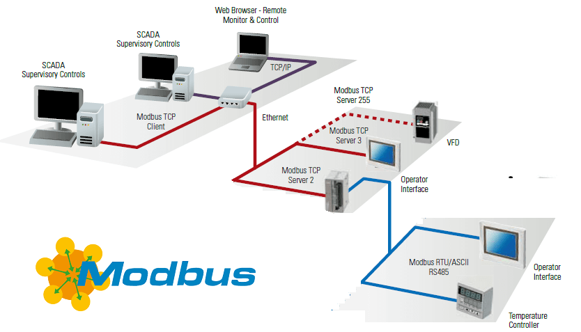
Modbus
According to Wikipedia, Modbus is a communications protocol located at levels 1, 2 and 7 of the OSI Model, based on the master/slave (RTU) or client/server (TCP/IP) architecture, designed in 1979 by Modicon for its range of programmable logic controllers (PLCs).
Converted into a de facto standard communications protocol in the industry, it is the one with the highest availability for the connection of industrial electronic devices.
Let's see some relevant information about Modbus:
- Each device on the Modbus network has a unique address.
- Any device can send Modbus commands, although it is usually allowed only by a master device.
- Each Modbus command contains the address of the device receiving the order.
- All devices receive the frame, but only the recipient executes it (except for a special mode called "Broadcast").
- Each of the messages includes redundant information that ensures its integrity at reception.
- The basic Modbus commands allow you to control an RTU device to modify the value of its registers or to request the content of these registers.

Arduino Automation Libraries
Now we know a little more about Modbus, we are going to program our Arduino based PLC industrial!
As we know, the Dallas DS18B20 temperature sensor works with the 1-Wire protocol, so we will need two libraries to be able to get the temperature:
For the Modbus protocol, we will need the library from Industrial Shields:
Arduino Code
// Include the libraries we need
#include <OneWire.h>
#include <DallasTemperature.h>
#include <RS485.h>
#include <ModbusRTUSlave.h>
//Sensor Pin: 2
#define ONE_WIRE_BUS 2
#define RS485_RATE 9600UL
OneWire oneWire(ONE_WIRE_BUS);
// Pass our oneWire reference to Dallas Temperature.
DallasTemperature sensor(&oneWire);
#define numAnalogInputs 1
uint16_t analogInputs[numAnalogInputs];
//Slave Address: 1
ModbusRTUSlave modbus(RS485, 1);
In the setup function, we are going to do the following:
· Initialize the serial port, the RS485 and the sensor.
· Set input registers to the slave instance.
void setup(void)
{
  // Start serial port
  Serial.begin(9600);
  // Start up the library
  sensor.begin();
  RS485.begin(RS485_RATE, HALFDUPLEX, SERIAL_8N1);
  modbus.begin(RS485_RATE);
  modbus.setInputRegisters(analogInputs, numAnalogInputs);
}
Finally, in the loop function we are going to write the following in order to request the temperature every, 10000 milliseconds while the PLC Modbus instance is constantly updating to set the input registers.
void loop(void) {
  static uint32_t lastStatusTime = millis();

  if (millis() - lastStatusTime > 10000) {
    sensor.requestTemperatures(); // Send the command to get temperatures
    float temp = sensor.getTempCByIndex(0);
    analogInputs[0] = temp * 100;
    Serial.println(analogInputs[0]);
    lastStatusTime = millis();
  }
  modbus.update();
}
Now your code is done, download the Industrial Shields boards as shown HERE >>> . Then, just select your board, model and port from the Tools menu.
In our case:
- Board: Industrial Shields boards > Ardbox family.
- Model: Ardbox Analog HF+ w/ HW RS-485.
Once everything is ready, upload your sketch, open the serial monitor, and check out the temperature from your Dallas sensor!
PLC Modbus Tutorial: How to get temperature with a Dallas sensor