
Introduction
In this post, you are going to learn more about working with an industrial PLC from Industrial Shields and the computer application LabVIEW.

Previous readings
We recommend you read the following posts from our blog before reading this one.
How to instal LabVIEW, NI VISA and VI Package Manager
Industrial Arduino based PLC programmed with LabVIEW
Industrial Arduino based programming with LabVIEW
Requirements
In order to work with the LabVIEW PC application, you will need the following items:
- Industrial Shields programmable logic controllers:
- Some electronic components such as wires, leds, resistors, potentiometers, etc.
Arduino IDE Software
Hardware & Software
Switch Configuration:
Most of the inputs and the outputs are connected to the internal Arduino, but in a few cases, the user can choose between a special peripheral configuration or a GPIO by changing the position of the Dip Switches.
Each switch can select only one of the two possible configurations at the same time. For example, in this case, we are watching the configuration of an M-Duino 42+ Ethernet industrial controller. If we set the switch to the right position (ON), the digital outputs Q0.5, Q0.6 and Q0.7 will be activated, but if the switch is in the left position (OFF), the analog outputs A0.5, A0.6 and A0.7 will be activated.
In this case, all of the switches have to be in the ON position.

Q0.5, Q0.6 & Q0.7 enabled - A0.5, A0.6 & A0.7 disabled
Connection between an Arduino board and LabVIEW:
First of all, you will look for the sketch called LIFA_Base following the steps in the first screenshot: Este equipo -- Disco local(C:) (or the letter that your local disc has) -- Archivos de programa (x86) -- National Instruments -- LabVIEW 2019 (or the version you downloaded) -- vi.lib -- LabVIEW Interface for Arduino -- Firmware -- LIFA_Base. Once you found it, click on it and an Arduino IDE window is going to pop up in your computer.

After that, go to this window and click Tools -- Board (Your PLC family) + Model (Your PLC) + Port and select your PLC Arduino family, your specific model and the serial port where it is located and transfer the code to your Industrial Shields PLC with the arrow on the top left of the screen (second icon).

Build the following electrical circuit:
The led can be any color. (The long leg of the led is the positive part, which has to be connected to the PLC pin (grey-red cable) and the other one has to be connected to the ground pin (GND) of the PLC controller through the resistor).
The connection of the led can be done in any of the digital outputs of the PLC. The equivalence of the pins of the Arduino board with your PLC for industrial automation is in our webpage, selecting your family and model and going into the file named User Guide in the Pinout section.
The resistance of the led must be 220 Ohm.
There has to be a cable that connects two pins in the controller Arduino; the so-called 5Vdc with the QVdc of the pins you are going to use.
A power supply (12-24 Vdc) is needed to turn on your programmable logic controller (PLC) apart of the USB connection from it to your computer.


The next step will be to open your LabVIEW application to work with it. Go to Este equipo -- Disco local(C:) (or the letter that your local disc has) -- Archivos de programa (x86) -- National Instruments -- LabVIEW 2019 (or the version you downloaded) -- Examples -- MakerHub -- LINX. Click on LINX - Blink (Simple) or LINX - Analog Read 1 Channel.

A window will pop up. Go to window -- Tile Left and Right and you will have the sketch of this project on your screen.
The next step will be to build your first LabVIEW program, starting from one of these examples. This video will help you to do it.
Once done, it will look like this: 
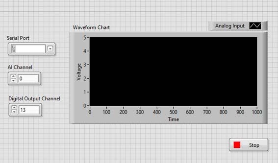


Click on the white arrow (top left of the screen) and the program is going to start running. Select the correct number of the pins you choose for the analog input (A0 in this case) and PWM output (5 in this case) and it should start running.
To see the evolution of the voltage and the different light intensity, move the potentiometer frome one side to the other and look at your LabVIEW graph and the led.
To stop the program, click on the Stop button in your program or the one that LabVIEW already provides (top left of the screen).
