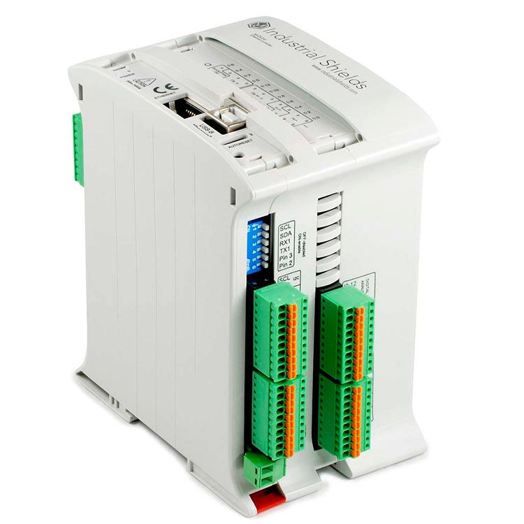
In industrial automation, establishing effective communication between devices is essential. This post focuses on the practical aspects of integrating a USB to RS232 adapter with an Arduino based PLC. We will see the necessary steps, from connecting the hardware to programming, to properly communicate a PC or another USB capable device with an M-Duino using the RS232 protocol.
Requirements
Connections
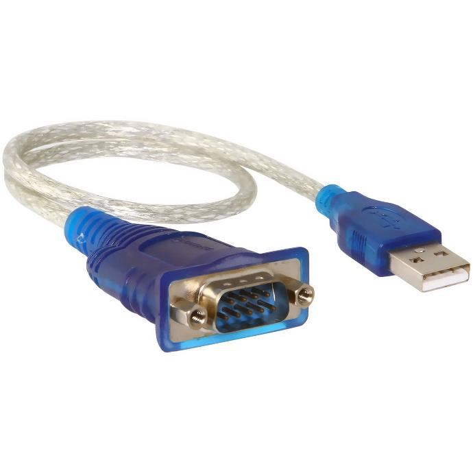
For this tutorial we are using a RS232 to USB adapter features a DB9 connector which has 9 pins numbered from 1 to 9. For this tutorial we will be using 3 pins: RX (pin 2), TX (pin 3) and GND (pin 5). In the M-Duino's case, the TX, RX and GND pins will be used. The following diagram illustrates how to connect the M-Duino PLC to the RS232 adapter:
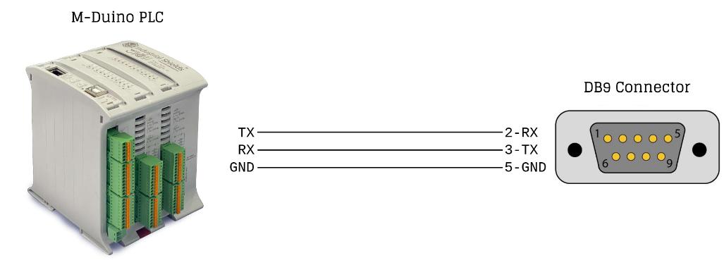
M-Duino setup
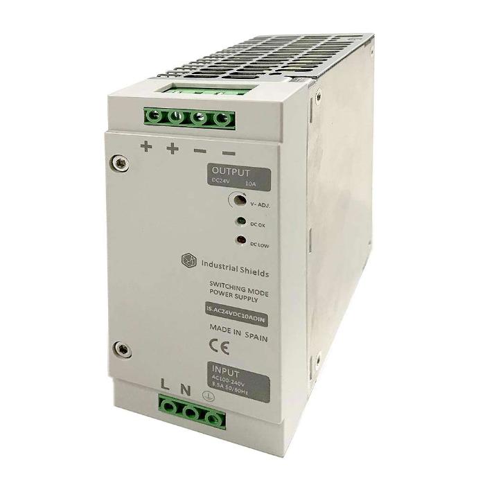
The first requirement for the RS232 communication to work is to properly power the PLC using a 12-24Vdc power supply. When the PLC is properly powered and the connections seen in the previous section are done, all that is left is to program the PLC.
We will be using the RS232 library included with our boards package. If you do not have it yet, you can install it following this tutorial. Remember to select your PLC model in the IDE.
Program example
Check the following example, which implements bidirectional communication. Characters written in the Arduino serial monitor will be printed on it as well as sent through RS232. Received messages will also be printed in the serial monitor.
Note that in the RS232.begin() function the baudrate used in the communication needs to be specified: in this case, 115200. The PLC and the USB-RS232 device need to be working at the same baudrate for the communication to work. There are also some additional parameters which can be configured:
- Data bits: 8 default.
- Stop bits: 1 default.
- Parity: none default.
These parameters can be changed adding a second argument to the begin function. For example: RS232.begin(115200, "SERIAL_8N2") where "8N2" means the following:
- 8 data bits
- No parity
- 2 stop bits
#include<RS232.h>

void setup() {
  // put your setup code here, to run once:
  Serial.begin(115200);
  RS232.begin(115200);
}

void loop() {
while (RS232.available()) {
Serial.println(RS232.read());
} while (Serial.available()) {char a = Serial.read();
RS232.write(a);
Serial.print(a);
}
}
USB-RS232 adapter setup
The USB-RS232 adapter can be used with any terminal emulator to test the serial communication:
- On Windows, programs such as TeraTerm can be used.
- On Linux, Picocom or other terminal emulators can be used.
When the USB device is connected to the PC, a port should be available: COMX in windows and /dev/ttyUSBX in Linux. Identify your device and then access it using your preferred terminal emulator.
In this case we will be using Picocom. The following command can be used to open a connection with a 115200 baudrate:
picocom /dev/ttyUSB0 -b 115200
The default configuration is 8 data bits, 1 stop bit and no parity. The --echo flag can be specified so that the terminal prints every message we send through it, as well as the received ones.
Demonstration
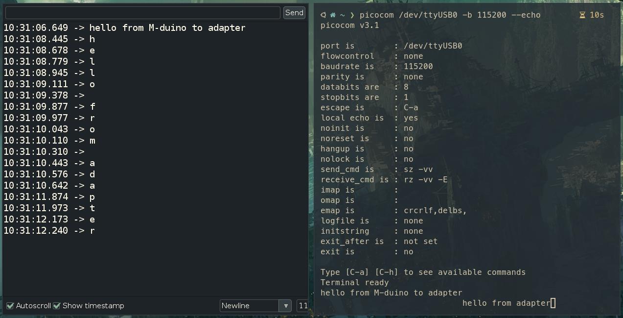
With what we learnt on this post we can successfully communicate using RS232. Check the following capture: the left window is the Arduino serial monitor, and the right one is Picocom. Messages can successfully be sent in both directions.
How to communicate an Arduino based PLC using a USB-RS232 adapter