
SPI (Serial Peripheral Interface) is a synchronous serial communication protocol commonly used to connect a master device to one or more peripherals. Compared to I2C, SPI is faster and simpler: instead of device addresses, it uses one dedicated Chip Select (CS) wire per slave to choose which device to communicate with. This article shows how to connect a master M-Duino PLC to two slave M-Duino PLCs over SPI and control their digital outputs from the master.
What you need
- Three M-Duino PLCs (one master, two slaves)
- Power supply
Wiring the SPI bus
The three PLCs share MISO (50 SO), MOSI (51 SI), and SCK (52 SCK) on the same bus. Each slave has its own dedicated Chip Select pin connected to the master:
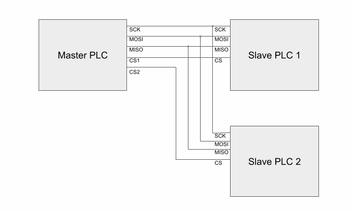
In this example the master uses Pin 2 as CS_1 (for slave 1) and Pin 3 as CS_2 (for slave 2). Refer to your M-Duino user guide for all available CS pins on your model.
Master sketch
The master alternates between activating slave 1 and slave 2 every second by sending one byte (1 = HIGH, 0 = LOW) to the selected slave via its Chip Select pin.
#include <SPI.h>

#define CS_1 2
#define CS_2 3

void setup() {
  pinMode(CS_1, OUTPUT);
  pinMode(CS_2, OUTPUT);
  SPI.begin();
}

void send_order(uint8_t CS, uint8_t action) {
  digitalWrite(CS, LOW);
  SPI.transfer(0);
  SPI.transfer(action);
  digitalWrite(CS, HIGH);
}

void loop() {
  send_order(CS_1, 1);
  send_order(CS_2, 0);
  delay(1000);

  send_order(CS_1, 0);
  send_order(CS_2, 1);
  delay(1000);
}
The send_order() function pulls the selected CS pin LOW, transfers a dummy byte followed by the action byte, then releases CS HIGH. Sending 1 sets the slave output HIGH; sending 0 sets it LOW.
Slave sketch
Both slaves run the same code. The slave listens for incoming SPI data using an interrupt service routine (ISR) and writes the received byte directly to output Q0_0.
#include <SPI.h>

#define CS 2

void setup() {
  pinMode(CS, INPUT_PULLUP);
  SPCR |= _BV(SPE);      // Habilita SPI en modo esclavo
  SPI.attachInterrupt(); // Habilita la interrupción SPI
}

ISR(SPI_STC_vect) {
  digitalWrite(Q0_0, SPDR); // Escribe el byte recibido en la salida
}
SPCR |= _BV(SPE) sets the SPI Enable bit in the SPI control register, configuring the device as a slave. SPI.attachInterrupt() enables the SPI transfer-complete interrupt. Each time the master sends a byte the ISR fires and writes SPDR (the SPI data register) to Q0_0.
Sending data back to the master
If a slave needs to return data to the master, modify SPDR inside the ISR before the transfer completes:
ISR(SPI_STC_vect) {
  if (SPDR == 1) {
    SPDR = 10;
  } else {
    SPDR = 20;
  }
}