Index
1. Introduction
2. Previous reading
3. Requirements
4. Configuring the switches
5. Output types
6. Hardware
7. Software
8. Example
9. Basics: Digital outputs in Arduino PLC
Introduction
In this post, we are going to explain how to do the basics in order to work with digital outputs of Industrial Shields' programmable logic controllers. Reading this post, you will be able to understand how to connect and configure the digital outputs of your industrial Arduino PLC controller.
Previous reading
We recommend you read the following posts in order to understand the program of this blog. We used the following blog posts to do this example:
How to program our industrial PLC with Arduino IDE: Installing the Industrial Shields's boards in the Arduino ID.
Requirements
In order to work with digital outputs you will need any of our industrial controllers for industrial automation:
Industrial Shields controllers:
Configuring the switches
Most of the digital outputs are always connected to the internal Arduino, but in a few cases, the user can choose between a special peripheral configuration or a GPIO by changing the position of the Dip Switches.
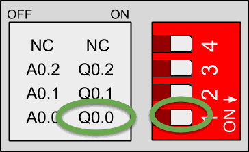
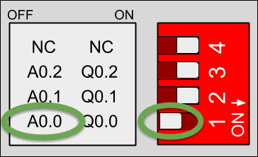
Each switch can select only one configuration. For example, in this case, we are watching the GPIOs configuration of an M-Duino 21+. If we put the switch to the right position (ON) in the lower one, the output Q0.0 will be activated and we will be able to work this as digital. If the switch is in the left position (OFF) we will activate the output as analog. Keep in mind each switch has two different configurations: you must select the right (ON) or the left (OFF) option.

Q0.0 enabled - A0.0 disabled

Q0.0 disabled - A0.0 enabled
Output types
In all of the Industrial Shields Arduino based PLCs, digital outputs can work at:
5V -24V digital output
Digital outputs have a special draw in the case of the PLC. Keep in mind that the output that can handle PWM is the same as the other digital outputs, but we will talk about it in another blog post:

Digital output

Digital output (PWM optional)
Hardware
All the digital outputs are optoisolated (they use the same GNDs as the PLC). The image below shows how to connect a digital output to the PLC:
.png?access_token=e04945ca-8155-4817-ae82-3be22de744c6)
5Vdc - 24Vdc Digital output
Software
In order to program the digital outputs, we must keep in mind that we can write the values with the following command:
digitalWrite(GPIO,value);This function writes a "HIGH" or "LOW" in the "GPIO" selected. Imagine we want to write a "HIGH" in the "Q0.6" output, then, we must write this line:
digitalWrite(Q0_6,HIGH);We must know we do not need to configure the digital outputs as digital. Industrial Shields' libraries do all the work for us.
Example
You can see a digital GPIO written in the following paragraph:
// Digital write example// Set the speed of the serial port
// This example writes the Q0_0 and shows via serial the value
// Setup function
void setup()
{Serial.begin(9600UL);
pinMode(Q0_0,OUTPUT); // Only required in ESP32 family products}Serial.println("1");
// Loop function
void loop()
{
digitalWrite(Q0_0, HIGH);Serial.println("0");digitalWrite(Q0_0, LOW);}
Basics about digital outputs of an industrial PLC