Pinout and I/O mapping on M-Duino and Ardbox
Every input and output on an M-Duino or Ardbox is exposed through the named pin constants you used in the previous lesson, such as I0_0 or Q0_0. This lesson maps where those pins physically sit on each board family, so wiring and code line up without guesswork.
What you will learn
- Read the I, Q, A and R naming convention.
- Find the terminal that matches a name in your code, on M-Duino and Ardbox.
- Know when to stop and check the diagram of your exact model before wiring.
Reading the labels
The first letter tells you the kind of terminal, and the digits identify it. As a general rule across the range, I labels inputs, Q labels digital outputs, A labels analog outputs and R labels relay outputs. Some inputs can also be read as analog values, depending on the model, so always confirm the function of each terminal on the diagram of your exact model.
M-Duino terminal layout
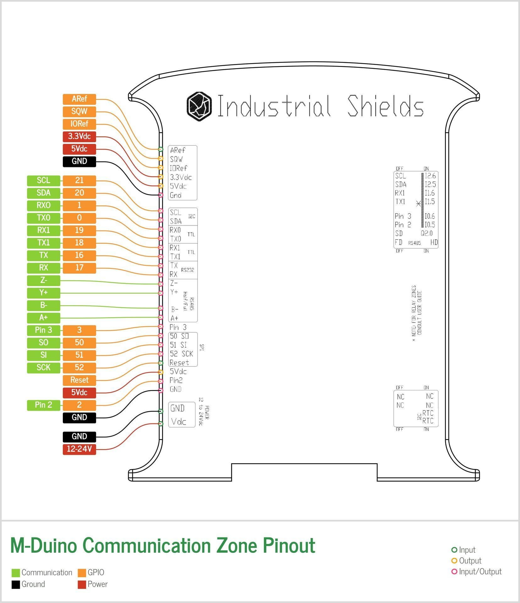
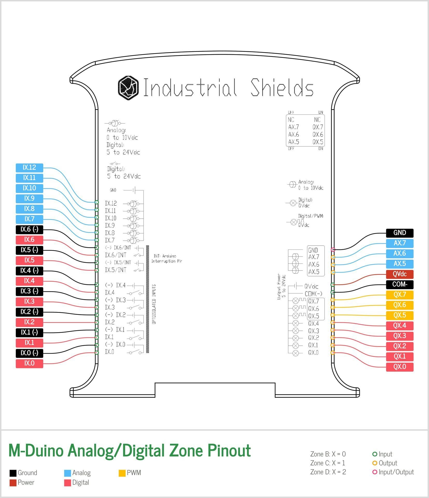
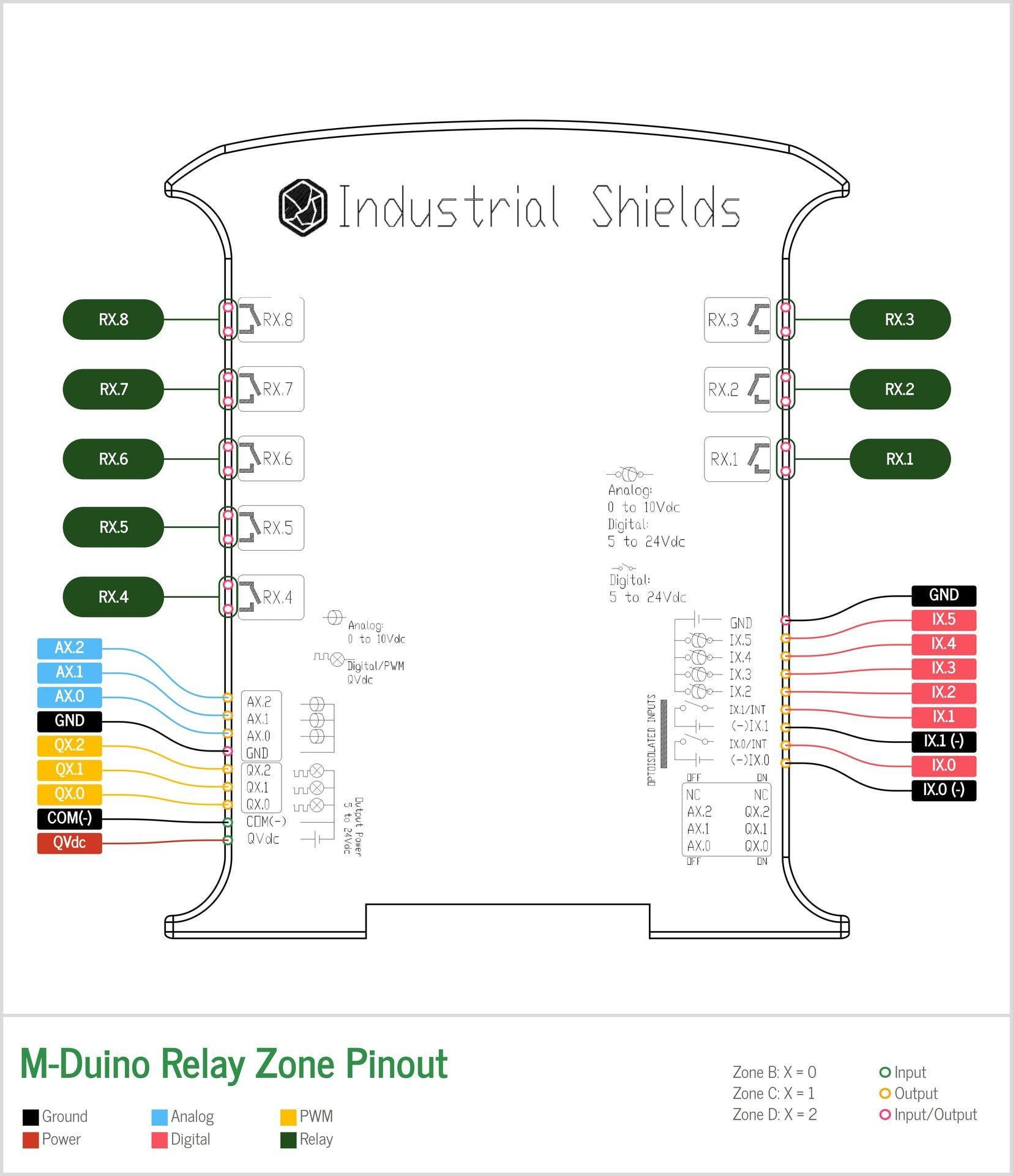
The M-Duino Ethernet range groups its terminals by function: communications, analog I/O, and relay outputs. Every variant in the range, 19, 21, 38, 42, 57 and 58, follows the same labeling convention. Only the terminal count changes.
Communications
Analog I/O
Relay outputs
Ardbox terminal layout
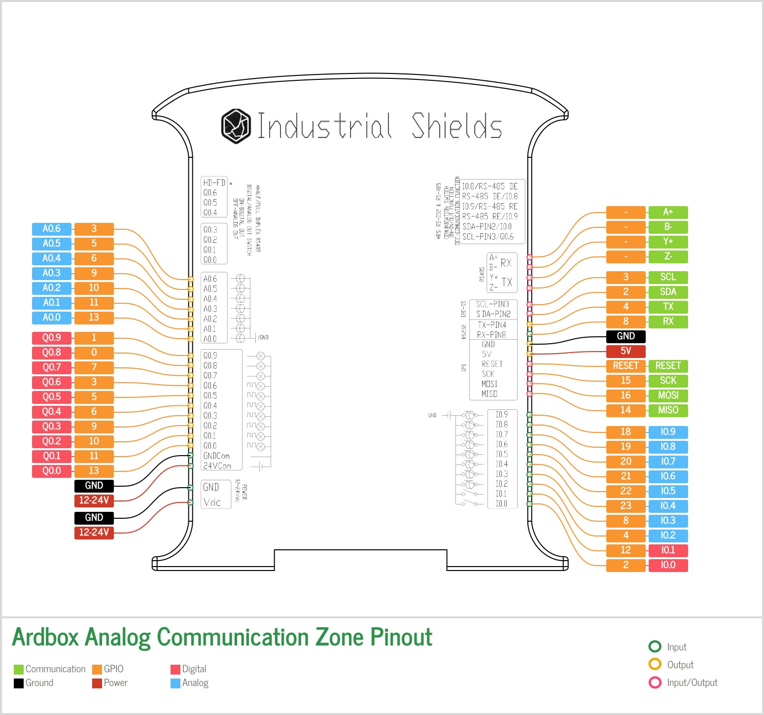
The Ardbox compact range follows the same I0_x, Q0_x and A0_x convention as the M-Duino, on a smaller terminal count.
Analog
Relay
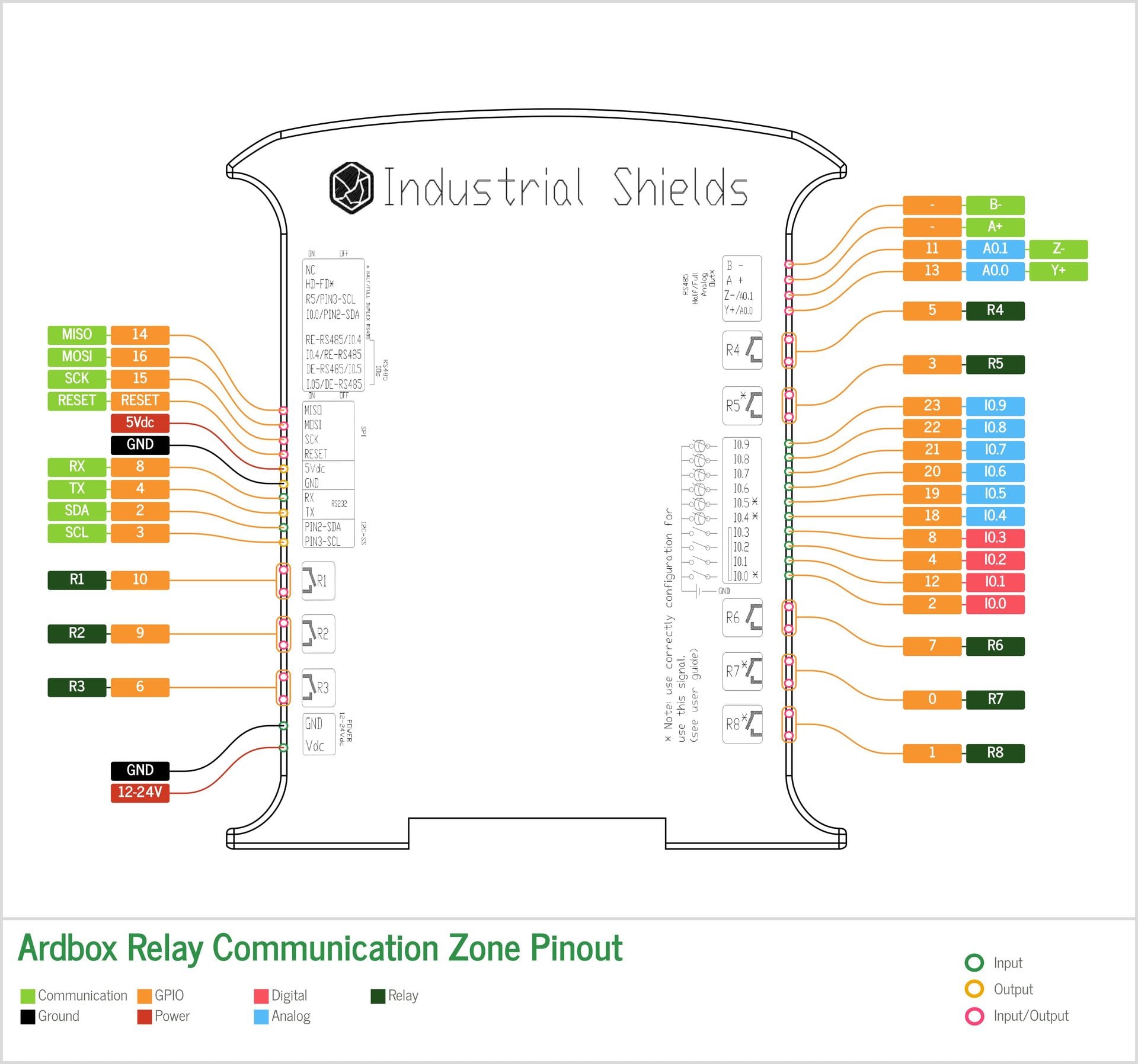
Variants with extra communication modules
If your exact PLC variant is not shown here, for example a DALI or GPRS variant, check the pinout diagram for that specific model before wiring. Additional communication modules can shift terminal numbering compared to the base range shown above.
Practice: map your own board
- Open the diagram of your exact model and locate the terminals for
I0_0andQ0_0. - Check that Q0_0 is the output that blinked in the previous lesson.
- Write down which terminal you would use for a 0 to 10 V sensor and which for a relay load, you will need them in the next lesson.
Check your understanding
- What does the letter Q tell you about a terminal?
That it is a digital output. - You own a model that is not in the diagrams above. What do you do before wiring?
Open the pinout diagram of that exact model, since extra modules can shift terminal numbering.
Next lesson: reading real sensors and driving real outputs with the four basic I/O calls.
There are no comments for now.
to be the first to leave a comment.