
Introduction
Modbus is a master-slave data communication protocol used worldwide with PLCs (Programmable Logic Controller). The Modbus protocol uses character serial communication lines or Ethernet as a transport layer. It supports communication to and from multiple devices connected to the same cable or Ethernet network. Raspberry PI PLC supports Modbus RTU (Remote Terminal Unit) via RS-485 and Modbus TCP via Ethernet.
In this blog post, we'll explore how to use Modbus RTU and TCP communication protocols with a Raspberry Pi PLC (Programmable Logic Controller) using Python 3 and Node-RED.
Requirements
To be able to follow these examples you might need some extra information linked on this posts:
How to work with RS485 with a Raspberry PLC
Take into account the Ethernet configuration of the Raspberry PLC that you can find on the UserGuide
Modbus RTU with Python 3
The following example shows how the master/slave communication is done using the pyModbus library. To test it you will need two Raspberry Pi PLC, one will act as the master and the other one as a slave.
To implement the slave, program the following code to a Raspberry PI PLC:
from pymodbus.server import StartSerialServer
from pymodbus.transaction import ModbusRtuFramer
from pymodbus.datastore import (
ModbusServerContext,
ModbusSequentialDataBlock,
ModbusSlaveContext
)
# Define a simple data block with 10 registers
store = ModbusSlaveContext(
di = ModbusSequentialDataBlock(0, [0x0]*10000),
co = ModbusSequentialDataBlock(0, [0x0]*10000),
hr = ModbusSequentialDataBlock(0, [0x0]*10000),
ir = ModbusSequentialDataBlock(0, [0x0]*10000))
context = ModbusServerContext(slaves=store, single=True)
# Start the Modbus RTU server on a serial port
# In this case using ’/dev/ttySC0’ port from Raspberry PLC 21
StartSerialServer(context=context,
port=’/dev/ttySC0’,
framer=ModbusRtuFramer,
baudrate=9600
)
On the other hand, program the following code in the other Raspberry PI PLC to implement the master:
from pymodbus.client import ModbusSerialClient
from pymodbus.transaction import ModbusRtuFramer
# Create a Modbus RTU client
client = ModbusSerialClient(method=’rtu’,
port=’/dev/ttySC0’,
baudrate=9600,
framer=ModbusRtuFramer)
# Connect to the Modbus RTU slave
client.connect()
# Define the slave address
slave_address = 0x00
# Write to holding registers
register_address = 0
num_registers = 5
data_to_write = [10, 20, 30, 40, 50]
response = client.write_registers(register_address,
data_to_write,
unit=slave_address)
if not response.isError():
print("Write successful")
else:
print("Error writing registers:", response)
# Read 5 holding registers starting from address 0
response = client.read_holding_registers(register_address,
num_registers,
unit=slave_address)
if not response.isError():
print("Read successful:", response.registers)
else:
print("Error reading registers:", response)
# Close the connection
client.close()
Before running both codes, ensure that the PLCs are powered correctly
and connected via RS485 ports (A+ with A+ and B- with B-). Please note
that in the example code, both devices' ttySC0 ports are used.
This implementation is a simple example to test the writing and reading of some registers from the master to the slave. If the communication is working you must see this output:
Write successful
Read successful: [10, 20, 30, 40, 50]
Modbus RTU with Node-RED
This program uses Node-RED to implement a master with Modbus RTU and uses the previous python code for the slave.
To test the example you can follow the next steps:
- Install the node-red-contrib-modbus node. You will see the Modbus nodes at your left.
- To implement the master, place the nodes and connect them as in the following figure.
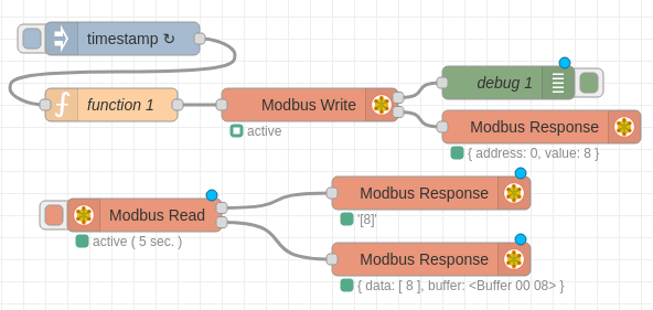
- Set up the ”Injection” node to send data every 5 seconds and write this code to the function node:
if (context.hasOwnProperty('num')) {
    context.num = context.num + 1;
} else {
    context.num = 0;
}

msg.payload = context.num;
return msg;
- In the ”Modbus Write” node:
- Configure the ”Server”: ”Type: Serial”, ”Serial port: /dev/ttySC0”, ”Serial type: RTU” and ”Baud rate: 9600”.
- Set the FC (Function Code) to ”FC 6: Preset Single Register” on the address 0.
- In the ”Modbus Read” node:
- Configure the ”Server” the same as the ”Modbus Write” node.
- Set the FC (Function Code) to ”FC 3: Read Holding Registers” on the address 0 with a quantity of 1 register and 5 seconds of poll rate.
This program will act as a master and will be writing and reading values of the register 0 from the slave. As a slave you can use the python code from the previous example.
Modbus TCP with Python 3
This is a program to test the Modbus TCP using the library PyModbus. Both master and slave codes are very similar to the Modbus RTU example with Python showed earlier and the program consists on writing and reading registers from master to the slave.
It is needed two Raspberry PI PLC and three Ethernet cables to run this test. Each PLC needs to be connected to a PC to be able to charge the codes and PLCs need to be connected between them. It is important to note that in the case of the Raspberry PI PLCs there are some differences between eth0 and eth1, so it indispensable to connect both PLC via the top Ethernet connector (or you can make your own Ethernet connections with the equivalent changes).
This is the slave code, which will create a TCP server at an address ”IP ADDRESS” and a port ”PORT”. Change them as your net configurations:
from pymodbus.server import StartTcpServer
from pymodbus.datastore import (
    ModbusServerContext,
    ModbusSequentialDataBlock,
    ModbusSlaveContext
)

# Define a simple data block with 10 registers
store = ModbusSlaveContext(
    di = ModbusSequentialDataBlock(0, [0x0]*10000),
    co = ModbusSequentialDataBlock(0, [0x0]*10000),
    hr = ModbusSequentialDataBlock(0, [0x0]*10000),
    ir = ModbusSequentialDataBlock(0, [0x0]*10000))
context = ModbusServerContext(slaves=store, single=True)

# Start the Modbus TCP server
# Change parameters to your host and port
StartTcpServer(context=context, address("IP_ADDRESS", PORT))
On the other hand, this is the master code, which will write and read some data from the slave. Before running the code remember to set the host and port as your net configurations.
from pymodbus.client import ModbusTcpClient
# Create a Modbus RTU client
# Change parameters to your host and port
client = ModbusTcpClient(host='IP_ADDRESS', port=PORT)
# Connect to the Modbus RTU slave
client.connect()
# Define the slave address
slave_address = 0x00
# Write to holding registers
register_address = 0
num_registers = 5
data_to_write = [10, 20, 30, 40, 50]
response = client.write_registers(register_address, data_to_write, unit=slave_address)
if not response.isError():
print("Write successful")
else:
print("Error writing registers:", response)
# Read 5 holding registers starting from address 0
response = client.read_holding_registers(register_address, num_registers, unit=slave_address)
if not response.isError():
print("Read successful:", response.registers)
else:
print("Error reading registers:", response)
# Close the connection
client.close()
Modbus TCP example with Node-Red
To communicate with Modbus TCP using Node-Red you can take the previous RTU Node-Red example and modify the settings of "Modbus Write" and "Modbus Read" nodes to TCP with your IP address and port. You can use the previous Modbus TCP python example code for the slave.
Modbus TCP and RTU examples for Raspberry PLC