
Introduction
RS-485, also known as EIA-485, is defined as a differential multi-point bus system; it is perfect to transmit data with high speed at ranges up to 12m. One of its most important features is that the twisted pair of wires reduces induced noise on the transmission line. Multiple receivers can be connected to such a network in a linear, multi-drop bus. These characteristics make RS-485 useful in industrial control systems and similar applications.
Our PLCs for industrial automation have the SC16IS752 integrated circuit inside. This is a low-power transceiver used for RS-485 communication that operates with a single power supply of 5V and the average current is 300μA. Using half-duplex communication to convert the TTL level to RS-485 level, it can reach the maximum transmission speed of 2.5Mbps.

In this post, you will learn how to do the basics to work with the RS485 of Industrial Shields Raspberry Pi programmable logic controllers. By reading this post, you will be able to understand how to connect and configure your industrial Raspberry Pi based PLC controller.
Previous readings
We recommend you to read the following posts in order to understand the program of this blog. We have used the following blog posts before making this example:
- How to access the Raspberry Pi PLC Read >>
- How to change the IP in Windows and Linux Read >>
- Basics about digital inputs of a Raspberry PLC Read >>
Requirements
In order to follow the blog and do all the corresponding tests we will need the following devices:
Hardware
Software
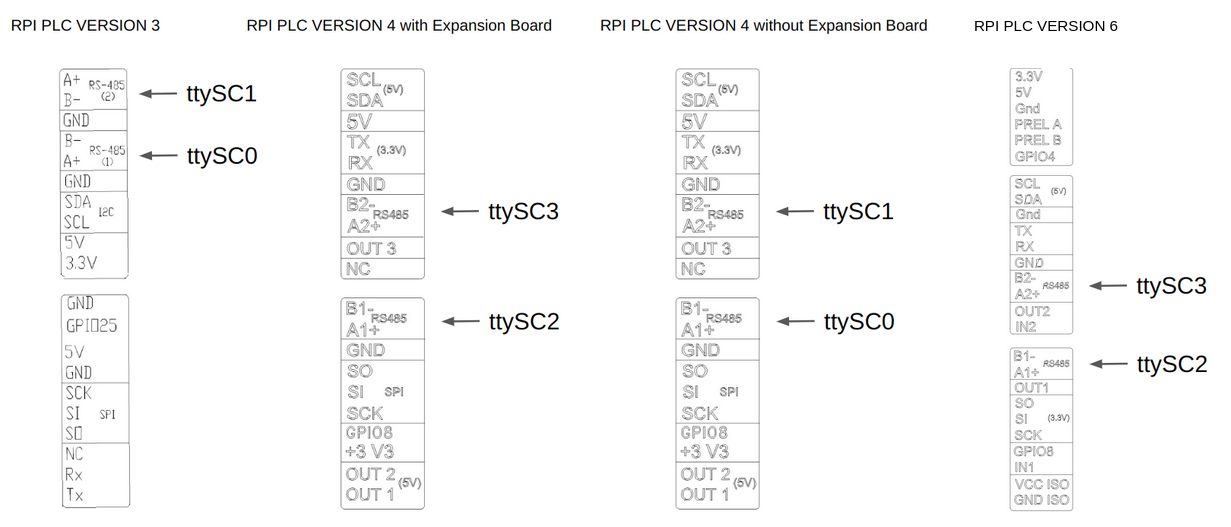
NOTE: For RPI PLC Version 4 and Version 6 you must use ttySC2 instead of ttySC0 and ttySC3 instead of ttySC1.
The Raspberry Pi industrial PLC uses the serial ports ttySC0 and ttySC1 to communicate. In this post, you will see how to communicate with an M-Duino Family PLC in order to send and receive data. First of all, you will do an initial test to check the RS485 in your Programmable Logical Controller.
Verification Test
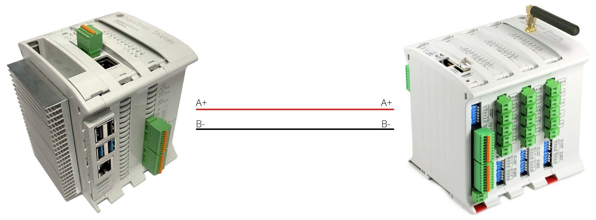
In the following test, you are going to use the two RS485 channels to communicate with each other, connecting A+ pin with the other A+ and B- to the B- pin of the same PLC. After connecting the wires, you will create a new bash script.
nano Test_RS485.sh
First of all, you will initialize both serial ports to the same baud rate of 115200.
#!/bin/bash

stty 115200 -F /dev/ttySC0 raw -echo #will be used to send data
stty 115200 -F /dev/ttySC1 raw -echo #will be used to receive data
All data received from the /dev/ttySC1 will be stored in the temporary file rs485.txt. You will send an "OK" message from the /dev/ttySC0, if everything is connected properly, it will be sent to the serial /dev/ttySC1 and written at rs485.txt. The resulting message will be stored in the RESULT variable for future verification. Be sure to kill the cat process, otherwise, it will run in the background.
cat /dev/ttySC1 > /tmp/rs485.txt &
sleep 1
echo "OK" > /dev/ttySC0
RESULT=$(cat /tmp/rs485.txt)
sudo killall cat > /dev/null
Finally, you will check if there is any data in the variable RESULT. If the communication has been successful, you will print on the terminal the received message "OK". Otherwise, a message error will be displayed.
if [ -n "${RESULT}" ] ; then
        echo rs485 true "${RESULT}"
else
        echo rs485 false "RS-485 cannot read from /dev/ttySC1"
fi
M-Duino connection test
After checking that both RS485 ports are working correctly, you will connect your Raspberry PLC to one of the M-Duino PLCs. In this case, we are using an M-Duino 54 ARA+. You will program your PLCs to send information from one to another and return a confirmation message. For the hardware connection, you must wire the A+ pin of the Arduino PLC to the A+ pin of the Raspberry PLC and also the B- with the B-.
// Include Industrial Shields libraries
#include <RS485.h>
//// IMPORTANT: check switches configuration
////////////////////////////////////////////////////////////////////////////////////////////////////
void setup() {
  // Begin serial port
  Serial.begin(9600);
  // Begin RS485 port
  RS485.begin(115200);
}
////////////////////////////////////////////////////////////////////////////////////////////////////
////////////////////////////////////////////////////////////////////////////////////////////////////
void loop() {
  // Wait bytes in the serial port
  if (Serial.available()) {
    byte tx = Serial.read();

    // Echo the byte to the serial port again
    Serial.write(tx);

    // And send it to the RS-485 port
    RS485.write(tx);
  }
}
////////////////////////////////////////////////////////////////////////////////////////////////////
#!/bin/bash

stty 115200 -F /dev/ttySC0 raw -echo #will be used to send data
end=$((SECONDS+5))

while [ $SECONDS -lt $end ]; do
	cat /dev/ttySC0 > /tmp/rs485.txt &
	sleep 1
	RESULT=$(cat /tmp/rs485.txt)
	if [ -n "${RESULT}" ] ; then
		echo "${RESULT}"
		break
	fi
done

sudo killall cat > /dev/null
  int Period = 1000; //Periode d'enviament de dades en ms
  int unsigned long Time;
  String rcv_message;
You must set up the following code on the loop function of the Arduino PLC:
////////////////////////////////////////////////////////////////////////////////////////////////////
void loop() {
  //Print received byte when available
  if (RS485.available()) {
    rcv_message = RS485.readString();
    Serial.println(rcv_message);
  }
}
////////////////////////////////////////////////////////////////////////////////////////////////////
As for the Raspberry side, you will have to create a new bash script and paste the following code:
#!/bin/bash

stty 115200 -F /dev/ttySC0 raw -echo #will be used to send data
echo "Hello World!" > /dev/ttySC0