Introduction
In a previous reading >, we wrote an output by using the XOD IDE, which is a free, open source and cross-platform visual programming language for microcontrollers and useful for industrial applications. It is also a PLC program.
In this blog post, we will be reading an input, both digital and analog, with this amazing open-source software and a PLC Arduino, thanks to Arduino automation!
Latest Posts
Requirements
- Industrial Arduino based PLC >
- Power Supply >
- B-type cable to program the industrial controller Arduino.
- Something to add some voltage to the input.
XOD.IDE
The XOD.IDE is an open source software to program microcontrollers such as Arduino boards, by using visual objects instead of text to code.
If you go to the XOD.IO website >, you will be able to either launch the browser IDE or download the desktop IDE.
Now, we are going to use the browser IDE, so that you can see that there is also an online version of the IDE to develop your application. So, click on Launch Browser IDE and let's start!
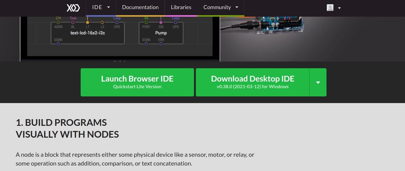
You will appear on the XOD.IO/IDE website, with its texts in the patch with a bit of explanation and even exercises to help you learn easily.
The large gray area with boxes and text is the program itself, where you will be programming. It is called a patch, and they are like documents or source files in other systems. A project is made by multiple patches.
On the left-hand side, you will find a list of patches grouped by a project or library name. The list of these patches is called a Project Browser. If you expand them, you will be able to find more.
Reading an Analog input
In this blog post, we are going to use the xod / gpio / analog-read patch in order to get the input values. Follow these steps:
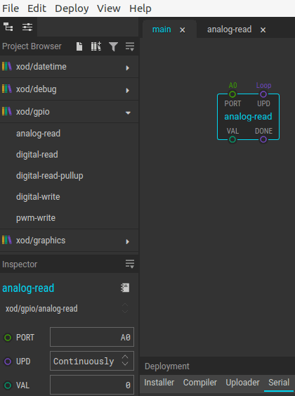
1. Expand the xod/gpio list, and drag and drop the analog-read node to the patch.
In the node configuration, select the Arduino pin that corresponds to the input of the PLC controller, and replace the A0 port with D + the one of your Programmable Logic Controller.
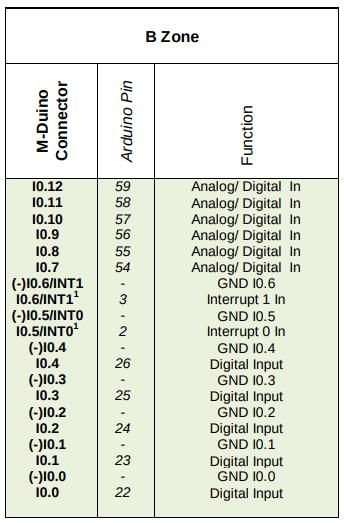
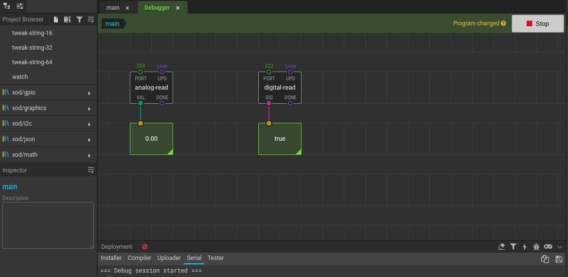
For example: In our case, we are using an M-Duino 21+ industrial PLC. If we want to test the I0.12 input, the Arduino pin which corresponds to that input is the 59. So, we will replace the A0 with D59.
2. Now, double-click on the analog-read node and on the not-implemented-in-xod node. By default, the lines 21 and 24 have this line:
emitValue<output_VAL>(ctx, ::analogRead(constant_input_PORT) / 1023.);
Remove: /1023. and replace them with the line below in order to get an analog value and not digital:
emitValue<output_VAL>(ctx, ::analogRead(constant_input_PORT));
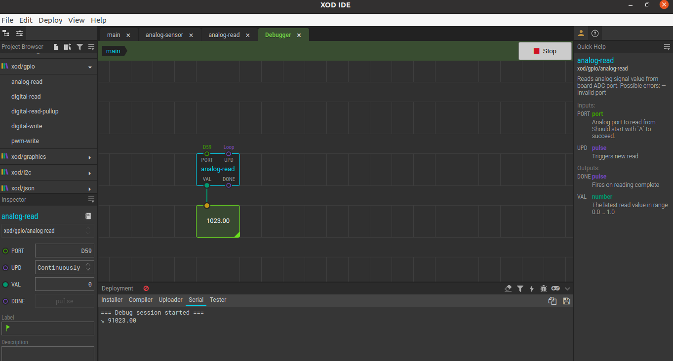
3. Go back to the patch, expand the xod/debug list, and drag and drop the watch node. Connect it to the VAL port from the analog-read node.
4. Go to the menu > Deploy > Upload to Arduino... > Select the Arduino Board of your Arduino based PLC > Select the Serial Port > Click on the check button: Debug after upload. And Upload.
5. Finally, add some voltage to the input, and get real-time values from your input!
Reading a Digital input
For the digital input, do the same without modifying any code.
1. Drag and drop the digital-read node. Modify the port by replacing the D0 with D22 (for input I0.0 in M-Duino21+).
In your case, replace D0 with the Arduino pin that corresponds to the input from the PLC that you want to test.
2. Add the xod/debug/watch node. Connect it to the SIG port of the digital-read node.
3. Click on Deploy > Upload to Arduino... > Select the Arduino Board of your Arduino based PLC > Select the Serial Port > Click on the check button: Debug after upload. And Upload.
4. Add some voltage to the I0.0 input and see how the watch node changes its state!
XOD.IO & Arduino based PLC: How to read an input