Introduction
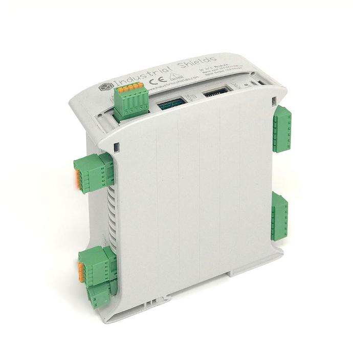
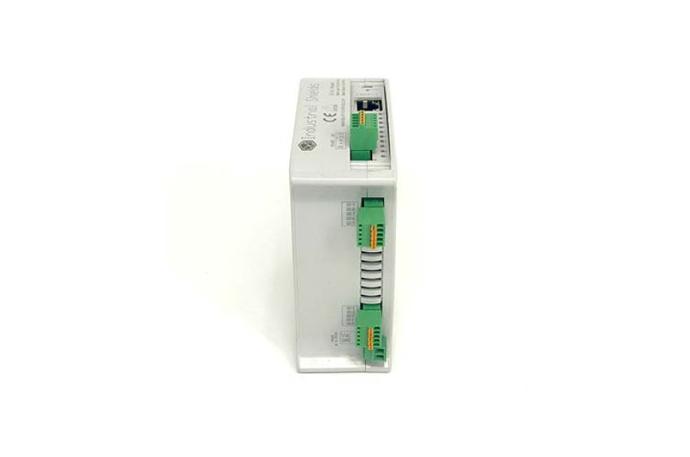
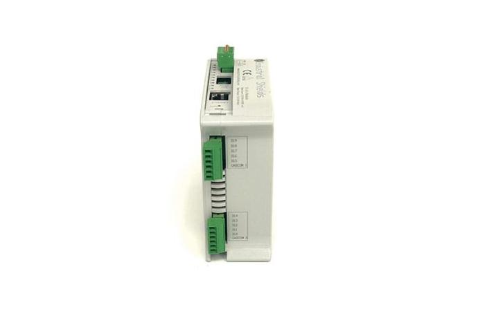
The Industrial Shields 10 I/O PLC is a versatile industrial controller offering a wide range of functionalities. In this article you will find information about its connection characteristics, including important parameters such as maximum switching frequency, rise and fall times, etc.
Requirements
The sketches used in this blog have been tested with the 10 I/Os Nano PLC, but these tests also work for 10 I/Os based on ESP microcontrollers.
Digital Outputs
The 10 I/Os PLC utilizes circuitry designed to interface with voltage ranging from 5-24 V, and every output incorporates opto-isolation circuitry.
void setup() {
  pinMode(Q0_0, OUTPUT);
  for(;;) {
    digitalWrite(Q0_0, HIGH);
    delay(10);
    digitalWrite(Q0_0, LOW);
    delay(10);
  }
}

void loop() {}
Using
this code without delay you will probably get a continuous signal. The rise times of these pins is 272µs, while the fall time is 228ms.
| Output Frequency | Period | Pulse Width | Delay |
| 2.174Hz | 460ms | 252ms | 230ms |
| 1.66Hz | 600ms | 324ms | 300ms |
Digital Inputs
The digital inputs of the 10 I/Os PLC can read input signals ranging from 0 to 3.3Vdc up to 24Vdc (or 10Vac), or even 220Vac with anti-polarity and over-current protections. Whichever option you choose, all the inputs will have opto-isolation with the PLC.
#define N_TIMES 10000
unsigned long t1, t2, t_max, t_average;
void setup() {
  Serial.begin(115200);
  pinMode(I0_5, INPUT);
  t_max = 0;
  t_average = 0;

  for (long i = 0; i<N_TIMES; i++) {
    t1 = micros();
    digitalRead(I0_5);
    t2 = micros();
    t_average += (t2-t1);
    if (t_max < t2-t1) t_max = t2-t1;
  }

  Serial.print("Max time: ");
  Serial.println(t_max);
  Serial.print("Average time: ");
  Serial.println(t_average/(float)N_TIMES);
}

void loop() {}
The delays between readings can go up to 20µs, while the average reading time is about 8.56µs.
Direct pins
SCL/SDA
These digital pins have an external pull-up resistor and operate at 5V. However, they can be used as both input or output. The rise and fall times of these pins is 2µs each.
Summary
Inputs
| Input type | Sampling frequency - Average | Sampling frequency - Highest read time |
| Digital (IX.0-9) | 116.8kHz (8.56µs) | 50kHz (20µs) |
| SCL/SDA | 116.8kHz (8.56µs) | 50kHz (20µs) |
Outputs
| Output type | Maximum stable frequency | Signal Frequency - Maximum | Rise time | Fall time |
| Digital (QX.0-9) | 2.174Hz (54.35%) | 2.174Hz (54.35%) | 272µs | 228ms |
| SCL/SDA | 155kHz (50%) | 49.507kHz (50%) | 2µs | 2µs |
Conclusion
To sum up, the 10 I/O PLC offers a wide range of functions and precise timing options, making it a robust and versatile choice for a variety of applications. When designing and implementing applications, it is essential to consider the different performance characteristics of the PLC's digital outputs, digital inputs, analogue outputs and analogue inputs.
By ensuring proper configuration and meticulous attention to these details, the 10 I/O PLC can deliver reliable and accurate results to meet your industrial automation and control needs.


Analysis of the 10 I/Os PLC's pinout time response