Introduction
Modbus is the most used pervasive communications protocol in industrial and building automation and the most commonly available means of connecting automated electronic devices.
Taking advantage of this, you learned to connect a Dallas DS18B20 temperature sensor. Then, you got the temperature from the Dallas sensor to your Arduino based PLC.
And now, you are going to connect it through Modbus with a Touchberry Pi 10.1", a Raspberry Pi panel PC, and make a very simple Dashboard with Node-RED!
Latest posts
Connections
.jpg?access_token=6f195a22-7cea-4922-9bb8-3d274ad3e11a)
Explanation
Read Input Registers
Modbus bases its data model on a series of tables that have distinguising characteristics. The four primary tables are:
| PRIMARY TABLES | OBJECT TYPE | TYPE OF | COMMENTS |
| Discrete inputs | Single bit | Read-Only | This type of data be provided by an I/O system. |
| Coils | Single bit | Read-Write | This type of data can be alterable by an application. |
| Input Registers | 16-bit word | Read-Only | This type of data can be provided by an I/O system. |
| Holding Registers | 16-bit word | Read-Write | This type of data can be alterable by an application program. |
The distinctions between inputs and outputs, and between bit-addressable and word-addressable data items, do not imply any application behaviour. It is perfectly acceptable, and very common, to regard all four tables as overlaying one another. For each of the primary tables, the protocol allows individual selection of 65536 data items, and read or write operations on those items are designed to span multiple consecutive data items up to a data size limit that depends on the transaction function code.
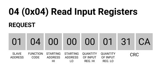
In this post, we are going to focus on the function code (FC) number 4, which has the following frame structure:
- Request:
- Slave Address (1 byte),
- FC (1 byte)
- Starting Address (2 bytes: from 0x0000 to 0xFFFF)
- Quantity of Input Registers (2 bytes: from 0x0001 to 0x007D)
- CRC
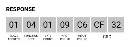
- Response:
- Slave Address (1 byte)
- FC (1 byte: 0x04)
- Byte count (1 byte: 2 x N*)
- Input Registers (N* x 2 bytes)
- CRC
In Node-RED, a request will be sent, a script will be executed that will process the information, in order to get a response with the temperature of your Dallas DS18B20 temperature sensor connected to an Arduino based PLC.

So, add an inject node and type this frame in a string msg.payload as shown in the picture blow. Then, wire it to an exec node where you will call a script to process the information.

Now, copy this script to your Touchberry Pi 10.1" industrial Panel PC and name as you want, like modbus.c, also remember that your must set the RS-485 rate to 9600UL.
// C library headers
#include <stdio.h>
#include <string.h>
// Linux headers
#include <fcntl.h> // Contains file controls like O_RDWR
#include <errno.h> // Error integer and strerror() function
#include <termios.h> // Contains POSIX terminal control definitions
#include <unistd.h> // write(), read(), close()
#include <stdlib.h>
#include <sys/stat.h>
#include <dirent.h>
#include <errno.h>
///////////////////////////////////////////////////////////////////////////////////////
// Convert char to int
int char2int(char input)
{
  if(input >= '0' && input <= '9') {
    return input - '0';
  }
  if(input >= 'A' && input <= 'F') {
    return input - 'A' + 10;
  }
  if(input >= 'a' && input <= 'f') {
    return input - 'a' + 10;
  }
  return 0;
}
///////////////////////////////////////////////////////////////////////////////////////
void hex2bin(const char* src, char* target)
{
  while(*src && src[1])
  {
    *(target++) = char2int(*src)*16 + char2int(src[1]);
    src += 2;
  }
}
///////////////////////////////////////////////////////////////////////////////////////
int main(int argc, char* argv[]) {
  char read_buf [256];
  int fd;
  if (argc < 2) {
    printf("Usage: %s <data-hex>\n", argv[0]);
    return 1;
  }
  char buf[100];
  hex2bin(argv[1], buf);
  int buflen = strlen(argv[1]) / 2;
  // Open the serial port. Change device path as needed (currently set to an standard FTDI USB-UART cable type device)
  int serial_port = open("/dev/ttyS0", O_RDWR);
  // Create new termios struc, we call it 'tty' for convention
  struct termios tty;
  // Read in existing settings, and handle any error
  if(tcgetattr(serial_port, &tty) != 0) {
      printf("Error %i from tcgetattr: %s\n", errno, strerror(errno));
      return 1;
  }
  tty.c_cflag &= ~PARENB;
 // tty.c_cflag &= ~PARODD; // Clear parity bit, disabling parity (most common)
  tty.c_cflag &= ~CSTOPB; // Clear stop field, only one stop bit used in communication (most common)
  tty.c_cflag &= ~CSIZE; // Clear all bits that set the data size
  tty.c_cflag |= CS8; // 8 bits per byte (most common)
  tty.c_cflag &= ~CRTSCTS; // Disable RTS/CTS hardware flow control (most common)
  tty.c_cflag |= CREAD | CLOCAL; // Turn on READ & ignore ctrl lines (CLOCAL = 1)
  tty.c_lflag &= ~ICANON;
  tty.c_lflag &= ~ECHO; // Disable echo
  tty.c_lflag &= ~ECHOE; // Disable erasure
  tty.c_lflag &= ~ECHONL; // Disable new-line echo
  tty.c_lflag &= ~ISIG; // Disable interpretation of INTR, QUIT and SUSP
  tty.c_iflag &= ~(IXON | IXOFF | IXANY); // Turn off s/w flow ctrl
  tty.c_iflag &= ~(IGNBRK|BRKINT|PARMRK|ISTRIP|INLCR|IGNCR|ICRNL); // Disable any special handling of received bytes
  tty.c_oflag &= ~OPOST; // Prevent special interpretation of output bytes (e.g. newline chars)
  tty.c_oflag &= ~ONLCR; // Prevent conversion of newline to carriage return/line feed
  // tty.c_oflag &= ~OXTABS; // Prevent conversion of tabs to spaces (NOT PRESENT ON LINUX)
  // tty.c_oflag &= ~ONOEOT; // Prevent removal of C-d chars (0x004) in output (NOT PRESENT ON LINUX)
  tty.c_cc[VTIME] = 1;    // Wait for up to 1s (10 deciseconds), returning as soon as any data is received.
  tty.c_cc[VMIN] = 0;
  // Set in/out baud rate to be 9600
  cfsetispeed(&tty, B9600);
  cfsetospeed(&tty, B9600);
  // Save tty settings, also checking for error
  if (tcsetattr(serial_port, TCSANOW, &tty) != 0) {
      printf("Error %i from tcsetattr: %s\n", errno, strerror(errno));
      return 1;
  }
// Export the desired pin by writing to /sys/class/gpio/export
  int dir = open("/sys/class/gpio/gpio27", O_WRONLY);
  if (ENOENT == errno) {
    /* Directory does not exist. */
//    write(dir, "27", 2);
    fd = open("/sys/class/gpio/export", O_WRONLY);
    if (fd == -1) {
      perror("Unable to open /sys/class/gpio/export");
      exit(1);
    }
    if (write(fd, "27", 2) != 2) {
      perror("Error writing to /sys/class/gpio/export");
      exit(1);
    }
  }
  close(dir);
// Set the pin to be an output by writing "out" to /sys/class/gpio/gpio27/direction
  fd = open("/sys/class/gpio/gpio27/direction", O_WRONLY);
  if (fd == -1) {
      perror("Unable to open /sys/class/gpio/gpio27/direction");
      exit(1);
  }
  if (write(fd, "out", 3) != 3) {
      perror("Error writing to /sys/class/gpio/gpio27/direction");
      exit(1);
  }
  close(fd);
  fd = open("/sys/class/gpio/gpio27/value", O_WRONLY);
  if (fd == -1) {
      perror("Unable to open /sys/class/gpio/gpio27/value");
      exit(1);
  }
  // Toggle LED 50 ms on, 50ms off, 100 times (10 seconds)
  if (write(fd, "1\n", 2) != 2) {
    perror("Error writing to /sys/class/gpio/gpio27/value");
    exit(1);
  }
  //usleep(10000);
///////////////////////////////////////////////////////////////////////////////////////////////////////////////////////////////
  if (write(serial_port, buf, buflen) < 0) {
	perror("Error writing to serial port");
	exit(1);
  }
int t = 10 * buflen * 1000000 / 9600;
usleep(t);
usleep(1000);
//tcdrain(serial_port);
///////////////////////////////////////////////////////////////////////////////////////////////////////////////////////////////
  if (write(fd, "0\n", 2) != 2) {
    perror("Error writing to /sys/class/gpio/gpio27/value");
    exit(1);
  }
  usleep(5000);
  close(fd);
  // Normally you wouldn't do this memset() call, but since we will just receive
  // ASCII data for this example, we'll set everything to 0 so we can
  // call printf() easily.
  //memset(read_buf, '\0', sizeof(read_buf));
  // Read bytes. The behaviour of read() (e.g. does it block?,
  // how long does it block for?) depends on the configuration
  // settings above, specifically VMIN and VTIME
//  char* num_bytes[] = {};
//  for (int i = 0; i < sizeof(read_buf); i++){
//    num_bytes[i] = read_buf[i];
//  }
char c;
int n;
char* ptr = read_buf;
int num_bytes = 0;
do {
	n = read(serial_port, &c, 1);
	if (n < 0) {
		perror("Read  serial port fail");
		exit(1);
	} else if (n > 0) {
		*ptr++ = c;
		++num_bytes;
	}
} while (n > 0);
  // n is the number of bytes read. n may be 0 if no bytes were received, and can also be -1 to signal an error.
  if (num_bytes < 0) {
      printf("Error reading: %s", strerror(errno));
      return 1;
  }
// Here we assume we received ASCII data, but you might be sending raw bytes (in that case, don't try and
// print it to the screen like this!)
// for (int i = 0; i < num_bytes; i++) {
//  printf("Read %i bytes. Received message: %s", num_bytes, read_buf);
// }
//  for (int i = 0; i < num_bytes; i++){
//  printf("Read %i bytes. Received message: %s", num_bytes, read_buf);
//  }
//printf("Received buffer (%d): ", num_bytes);
  for (int i = 0; i < num_bytes; ++i) {
    printf("%02x", read_buf[i]);
  }
  printf("\n");
  close(serial_port);
  return 0; // success
}
///////////////////////////////////////////////////////////////////////////////////////
Then, in the exec node, let's execute the modbus binary file you just compiled. Add the command to call the file in the path you put it and append the msg.payload with the frame to run the script with a parameter:

After executing the script, the response we got was: 01040109C6CF32. So, let's analize the frame:

What really matters, the data you are interested in, are the input registers, so 09C6. So let's get it with a function node and convert it to decimal, to get the temperature.
Now, add a function node with the following code:
var temp = msg.payload;
return {
    payload: parseInt(temp.substring(6,10), 16)/100
}write about products or services here, write about solutions.
In the function above, the parseInt with a base of 16 indicates a conversion to Hexadecimal. You do it only getting the substring from 6 to 10, so the data of the frame. Then, you divide it by 100 as we sent a uint16_t data from the Arduino code.

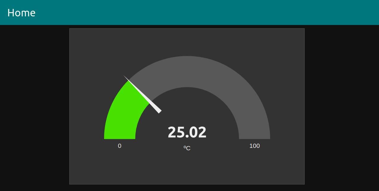
Add a debug node or a Dashboard Gauge node, and check your temperature using Modbus!

Node-RED & Touchberry Tutorial: How to get temperature from Dallas sensor