Introduction
In this blog post, we tell you how to use the analogue input of a PLC to determine the level of a tank.
By using this method, you will be able to reduce the number of digital inputs required, thus optimising the use of the PLC's resources.

Connection circuit
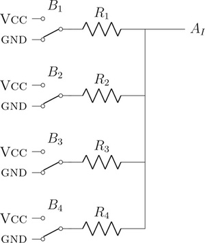
To connect the 4 buoys to an analogue input and still be able to determine the tank level, it is necessary to create a simple circuit. By connecting a suitable resistor between each buoy and the analogue input (AI), you can create a circuit such that the voltage at the input is different depending on the tank level and the active buoys. In this schematic, the buoys (B1, B2, B3 and B4) are characterised as a switch between Vdc and GND.

Let's analyse this circuit considering that B1 is the lowest buoy in the tank, and B4 is the highest. This means that there are 5 possible combinations, because if one buoy is active, all the buoys lower than it must be active as well. This table shows the 5 possible combinations and the resulting input voltage as a function of Vdc and the resistors:
| Active buoys (VCC) | Unactive buoys (GND) | Voltage at the input |
| None | B1, B2, B3, B4 | GND |
| B1 | B2, B3, B4 |
|
| B1, B2 | B3, B4 |
|
| B1, B2, B3 | B4 |
|
| B1, B2, B3, B4 | GND | Vcc |
Assuming there is only these 5 outputs simplifies analyzing the circuit. In reality, however, there are 16 possible outputs for this circuit, depending on all the combinations of buoys. The equations to calculate the output at the voltage are like the ones in the previous table, but changing the resistor values as it corresponds. Choosing adequate resistor values will allow us to identify all the combinations.
Furthermore, although the analog input can take up to 24V, the ADC can only read between 0-10V, which means voltages higher than 10V will be read as 10V only. The resistors need to be chosen so that the different voltage values fall within this range, with the exception of Vcc, which can be interpreted as 10V.
For example, taking these Vcc and resistor values, easily obtainable from standard resistors:
Vcc = 12v
R1 = 4.7kΩ
R2 = 3.7kΩ
R3 = 3.3kΩ
R4 = 2.2kΩ
The voltages obtained at the output for all the possible combinations are:
| B4 | B3 | B2 | B1 | Voltage (V) |
| 0 | 0 | 0 | 0 | 0 |
| 0 | 0 | 0 | 1 | 2.06 |
| 0 | 0 | 1 | 0 | 2.61 |
| 0 | 0 | 1 | 1 | 4.67 |
| 0 | 1 | 0 | 0 | 2.93 |
| 0 | 1 | 0 | 1 | 4.99 |
| 0 | 1 | 1 | 0 | 5.55 |
| 0 | 1 | 1 | 1 | 7.6 |
| 1 | 0 | 0 | 0 | 4.4 |
| 1 | 0 | 0 | 1 | 6.45 |
| 1 | 0 | 1 | 0 | 7.01 |
| 1 | 0 | 1 | 1 | 9.07 |
| 1 | 1 | 0 | 0 | 7.33 |
| 1 | 1 | 0 | 1 | 9.39 |
| 1 | 1 | 1 | 0 | 9.94 |
| 1 | 1 | 1 | 1 | 12 |
This way you can determine which buoys are active, and therefore, the tank level. Although 12V is higher than the ADC range, you can read it as 10V, as the value immediately above is lower.
Programming example
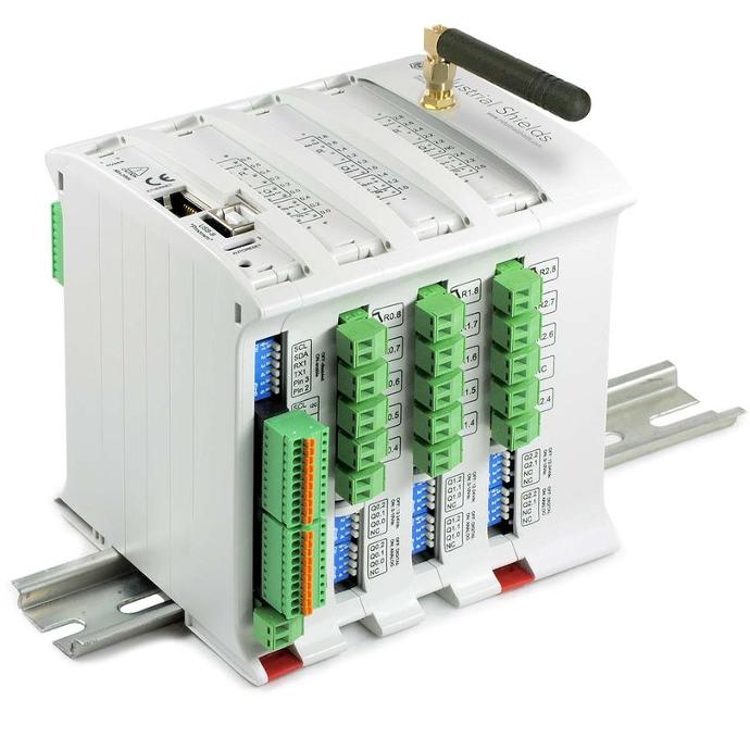
Let's see how you can program the PLC to recognise the tank level using the value of the analog input. This program example works for an M-DUINO PLC, but can easily be adapted to other platforms.
First you need to define the voltage levels provided by the buoys, which depend on the circuit configuration you saw earlier. In this example a macro is used to convert the expected voltage levels in the analog input to a 10-bit number, which is the resolution of the ADC in the case of the M-DUINO. Doing it this way with macros means the necessary calculations are computed on compile time, which saves resources.
Once the input has been read, you only need to perform some comparisons to determine the tank level. In this case the result is printed through the Serial.
#define CONVERSION(v) (1024*v/10)

#define V1 0
#define V2 2.06
#define V3 2.61
#define V4 4.67
#define V5 2.93
#define V6 4.99
#define V7 5.55
#define V8 7.6
#define V9 4.4
#define V10 6.45
#define V11 7.01
#define V12 9.07
#define V13 7.33
#define V14 9.39
#define V15 9.94
#define V16 12

void setup() {
  Serial.begin(115200);
}

void loop() {

  uint16_t read = analogRead(I0_12);

  Serial.println(read, DEC);

  if (read >= CONVERSION(10)) { // B1, B2, B3, B4
    Serial.println("Level 4");
  }
  else if (read >= CONVERSION(V15)) { // B2, B3, B4
    Serial.println("Error");
  }
  else if (read >= CONVERSION(V14)) { // B3, B4
    Serial.println("Error");
  }
  else if (read >= CONVERSION(V12)) { // B1, B2, B4
    Serial.println("Error");
  }
  else if (read >= CONVERSION(V8)) { // B1, B2, B3
    Serial.println("Level 3");
  }
  else if (read >= CONVERSION(V13)) { // B3, B4
    Serial.println("Error");
  }
  else if (read >= CONVERSION(V11)) { // B2, B4
    Serial.println("Error");
  }
  else if (read >= CONVERSION(V10)) { // B1, B4
    Serial.println("Error");
  }
  else if (read >= CONVERSION(V7)) { // B2, B3
    Serial.println("Error");
  }
  else if (read >= CONVERSION(V6)) { // B1, B3
    Serial.println("Error");
  }
  else if (read >= CONVERSION(V4)) { // B1, B2
    Serial.println("Level 2");
  }
  else if (read >= CONVERSION(V9)) { // B4
    Serial.println("Error");
  }
  else if (read >= CONVERSION(V5)) { // B3
    Serial.println("Error");
  }
  else if (read >= CONVERSION(V3)) { // B2
    Serial.println("Error");
  }
  else if (read >= CONVERSION(V2)) { // B1
    Serial.println("Level 1");
  }
  else {
    Serial.println("Empty");
  }

}
Conclusion
To sum up, measuring a tank's level with a PLC's analogue input has many advantages.
You can use a simple circuit with the right resistors to make the input voltage change depending on the tank level and the buoys that are on. This way, you will save digital inputs and use the PLC's resources better.
This technique will help you to watch and control tank levels in a simple and precise way.


How to measure tank level with the analogue input of an industrial PLC