Introduction
XOD.IO is a visual programming language for microcontrollers and industrial automation, which is free, open source, cross-platform and useful for PLC programming and industrial applications.
In this tutorial, we will be programming the Arduino based PLC: M-Duino 21+ to activate and deactivate an output with this amazing open-source software!
Latest Posts
Requirements
- M-Duino industrial PLC >
- Power Supply >
- B-type cable to program the M-Duino PLC controller or an industrial controller Arduino PLC.
XOD.IDE
The XOD.IDE is an open source software to program microcontrollers such as Arduino automation boards, by using visual objects instead of text to code.
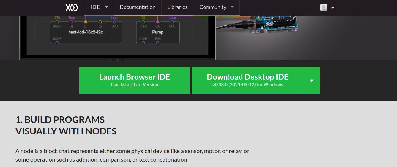
If you go to the XOD.IO website >, you will be able to either launch the browser IDE or download the desktop IDE.
Now, we are going to use the browser IDE, so that you can see that there is also an online version of the IDE to develop your application. So, click on Launch Browser IDE and let's start!

You will appear on the XOD.IO/IDE website, with its texts in the patch with a bit of explanation and even exercises to help you learn easily.
The large gray area with boxes and text is the program itself, where you will be programming. It is called a patch, and they are like documents or source files in other systems. A project is made by multiple patches.
On the left-hand side, you will find a list of patches grouped by a project or library name. The list of these patches is called a Project Browser. If you expand them, you will be able to find more.
Steps
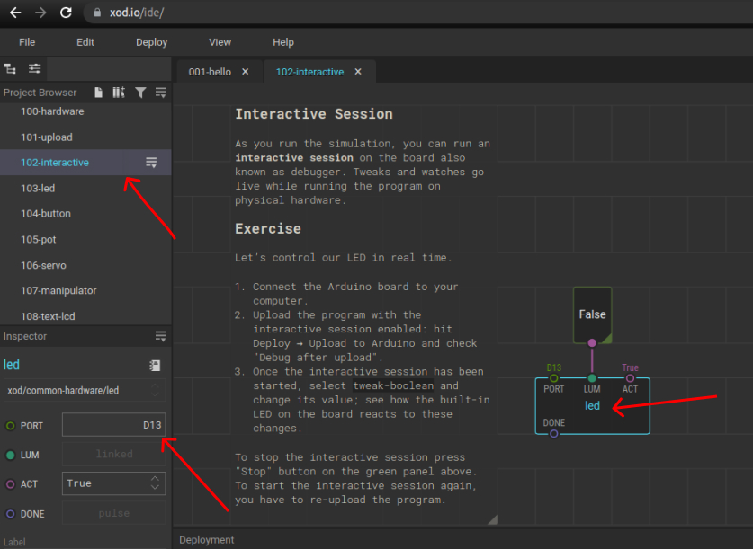
So, once we are in the 102-interactive patch, we have to find the field to change the pin to be able to activate and deactivate a concrete output.
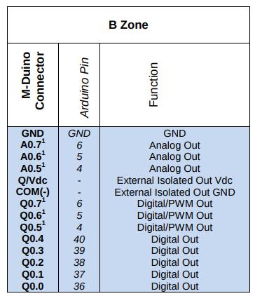
The M-Duino PLC has direct connections with the Arduino pins, as you can see in the following picture.
You can see more information in every user guide from the PLCs.

In the M-Duino pinout from above, you can see that the output Q0.0 belongs to the pin 36 Arduino Pin.
By default, it has set the built-in LED number 13.
So, we will change the D13 for D36 in order to set the digital output Q0.0 to HIGH.

Once the port number is changed, click on the False node, and in the parameters on the left, change the OUT value from False to True.
Finally, plug your M-Duino PLC Arduino and power it with the power supply. Go to Deploy > Upload to Arduino... > Select the board model: Arduino Mega ADK > Click on Refresh, in order to detect the Serial Port where the M-Duino PLC is connected to > Important: Click on Debug after upload > Upload.
Now, the Q0.0 output from your Programmable Logic Controller should turn on, since the tweak-boolean node is set to True. The debug mode allows you to change the value of the parameters dynamically without having to upload the code every time. So, change the tweak-boolean node to False, and see how it changes in your Arduino based PLC!
XOD.IO & Arduino based PLC: How to write an output