Introduction
The main OpenMote-B board includes an expansion port (8 pins with 2.54 mm spacing) that can be used for debugging or to connect daughter boards like the OpenMote-B sensors board. The expansion board includes a VCC (2.5V) and a GND pin, as well as six configurable pins.
In this blog post, we are going to use three of these six configurable pins to connect an Openmote B board with an Arduino based PLC through RS485.
Latest Posts
Requirements
- Arduino based PLC >>>
- Openmote B board >>>
- Wires
- Max485 from TTL to RS485 converter
- Power supply >>>
- B type cable to program the Arduino based PLC
1. How to connect the openmote B board to a MAX485 converter
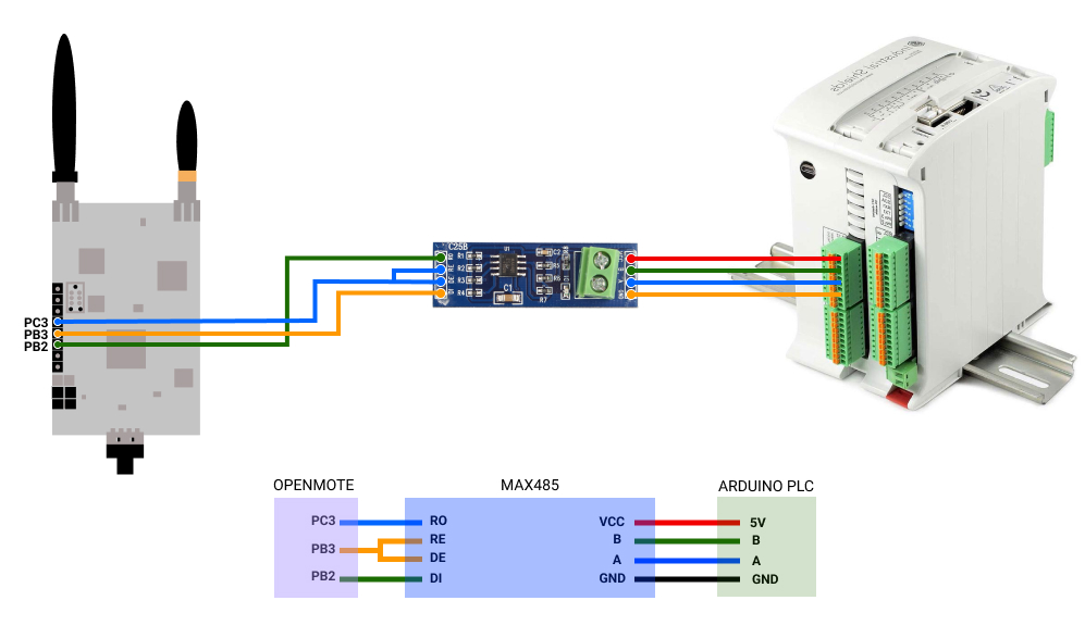
First of all, we are going to connect the wires as shown in the picture below.
Note that the antennas and batteries are not needed in the openmote. Also, power your Arduino based PLC.

2. Arduino code
Then, we will need to have the Arduino IDE installed in our computer, and also the Industrial Shields boards for programming our Arduino based PLC.
2- Go to the Menu > Tools > Board > Select your Industrial Shields Board.
3- Go to the Menu > Tools > Model > Select your Industrial Shields Board model.
4- Go to the Menu > Tools > Port > And select the one that you are connecting your PLC to.
5- Finally, paste the code below and Upload the sketch to the Arduino board.
/*
   Copyright (c) 2017 Boot&Work Corp., S.L. All rights reserved
   This program is free software: you can redistribute it and/or modify
   it under the terms of the GNU Lesser General Public License as published by
   the Free Software Foundation, either version 3 of the License, or
   (at your option) any later version.
   This program is distributed in the hope that it will be useful,
   but WITHOUT ANY WARRANTY; without even the implied warranty of
   MERCHANTABILITY or FITNESS FOR A PARTICULAR PURPOSE.  See the
   GNU Lesser General Public License for more details.
   You should have received a copy of the GNU Lesser General Public License
   along with this program.  If not, see <http://www.gnu.org/licenses/>.
 */

#if defined(HAVE_RS485)
#include <RS485.h>
#else
#define RS485 Serial2
#endif
#define RATE          9600UL
#define PERIOD        1000
#define DUPLEX        HALFDUPLEX
#define LEDS_ENABLED  0
#define SEND_LN       0
#if LEDS_ENABLED
#define LED_BLINK     20
#define TX_LED        Q0_0
#define RX_LED        Q0_1
#endif
unsigned long lastSent = 0;
unsigned long txPinStart = 0;
unsigned long rxPinStart = 0;
////////////////////////////////////////////////////////////////////////////////////////////////////
void setup() {
  Serial.begin(9600L);
  Serial.println("rs485-periodic-sender started");
#if LEDS_ENABLED
  pinMode(TX_LED, OUTPUT);
  pinMode(RX_LED, OUTPUT);
#endif
  RS485.begin(RATE, DUPLEX);
}
////////////////////////////////////////////////////////////////////////////////////////////////////
void loop() {
#if LEDS_ENABLED
  updateLeds();
#endif
  if (millis() - lastSent > PERIOD) {
    tx();
  }
  //rx();
}
#if LEDS_ENABLED
////////////////////////////////////////////////////////////////////////////////////////////////////
void updateLeds() {
  updateLed(TX_LED, txPinStart);
  updateLed(RX_LED, rxPinStart);
}
////////////////////////////////////////////////////////////////////////////////////////////////////
void updateLed(int pin, unsigned long startTime) {
  if (millis() - startTime > LED_BLINK) {
    digitalWrite(pin, LOW);
  }
}
#endif
////////////////////////////////////////////////////////////////////////////////////////////////////
void tx() {
  static uint8_t counter = 0;
  RS485.write(counter + '0');
#if SEND_LN
  RS485.write('\r');
  RS485.write('\n');
#endif
  lastSent = millis();
#if LEDS_ENABLED
  digitalWrite(TX_LED, HIGH);
  txPinStart = millis();
#endif
  Serial.print("TX: ");
  Serial.println(counter, HEX);
  counter = (counter + 1) % 10;
  RS485.flush();
}

////////////////////////////////////////////////////////////////////////////////////////////////////
void rx() {
  if (RS485.available()) {
    byte in = RS485.read();

#if LEDS_ENABLED
    digitalWrite(RX_LED, HIGH);
    rxPinStart = millis();
#endif

    Serial.print("RX: ");
    Serial.println(in, HEX);
  }
}
If you open the Serial monitor, you will see what you are sending: a counter from 0 to 9.
3. Openmote B code
a. First of all, visit this blog post and go to the second point called: 2. HOW TO DOWNLOAD OPENMOTE B FILES
b. Once listed, we will need to install docker-compose. Please, install it from here >>>
c. Then, inside the test folder, there is the folder called test-rs485-rx, which will be the project that we are going to execute.
So, from the openmote-fw/ folder, we will run the following command:
docker-compose run --rm openmote test-rs485-rx
d. Finally, install the screen if you do not have it:
sudo apt update
sudo apt install screen
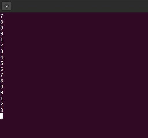
And check how you receive the counter from 0 to 9 that we are sending through our Arduino based PLC:
screen /dev/ttyUSB1 115200

Press Ctrl+a and \ to exit screen.
Make sure that the uart0 baud rate from the openmote code is the same as the baud rate of the screen running command. And that the uart1 baud rate from the openmote code is the same as the RS485 baud rate from the Arduino code.
RS485 & Openmote B Board