Introduction
In this post, we will talk about the SPI communication for our ESP32 based industrial PLCs. The SPI bus was developed by Motorola in 1980. It is currently a standard in the world of electronics and automation.
SPI stands for Serial Peripheral Interface, which is a synchronous serial communication interface used to communicate between microcontrollers and peripheral devices. It is a full-duplex, synchronous, and serial communication protocol.
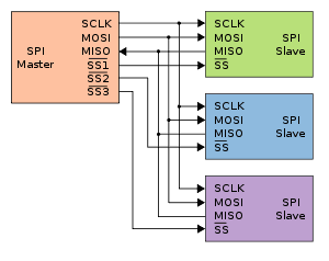
SPI uses a master-slave architecture in which one device (the master) initiates communication with one or more slave devices. The master device generates a clock signal and sends data to the slave devices in a serial fashion, and the slave devices respond by sending data back to the master.
The communication takes place on four wires:
- MOSI (Master Out Slave In): The master sends data to the slave using this line.
- MISO (Master In Slave Out): The slave sends data back to the master using this line.
- SCLK (Serial Clock): This is the clock signal generated by the master, which synchronizes the communication between the master and slave devices.
- SS (Slave Select, also called chip select): This signal is used by the master to select which slave device it wants to communicate with.
To initiate a communication, the master device first selects the slave device by pulling the SS signal low. The master then sends a series of clock pulses on the SCLK line, and on each clock pulse, it sends a bit of data on the MOSI line. The slave device receives the data on the MOSI line and sends its response back on the MISO line.
SPI communication can be configured to use different clock rates, data formats, and other parameters depending on the requirements of the devices being used. SPI is a popular communication protocol in embedded systems, as it is simple, fast, and reliable.

Requirements
In order to work with SPI, you will need any of our industrial programmable logic controllers ESP32 PLC for industrial automation:

Hardware
Make sure that your industrial PLC is properly powered (12-24 Vdc).
The ESP32 microcontroller has four SPI (Serial Peripheral Interface) ports, two of which are primary SPI ports, and the other two are secondary SPI ports. The two primary SPI ports are HSPI (SPI2) and VSPI (SPI3). They are general purpose SPI drivers, open to users. SP0 and SP1 are used internally to communicate with on-board flash memory, and therefore should not be used.
Remember that SPI communication operates at 3.3V.
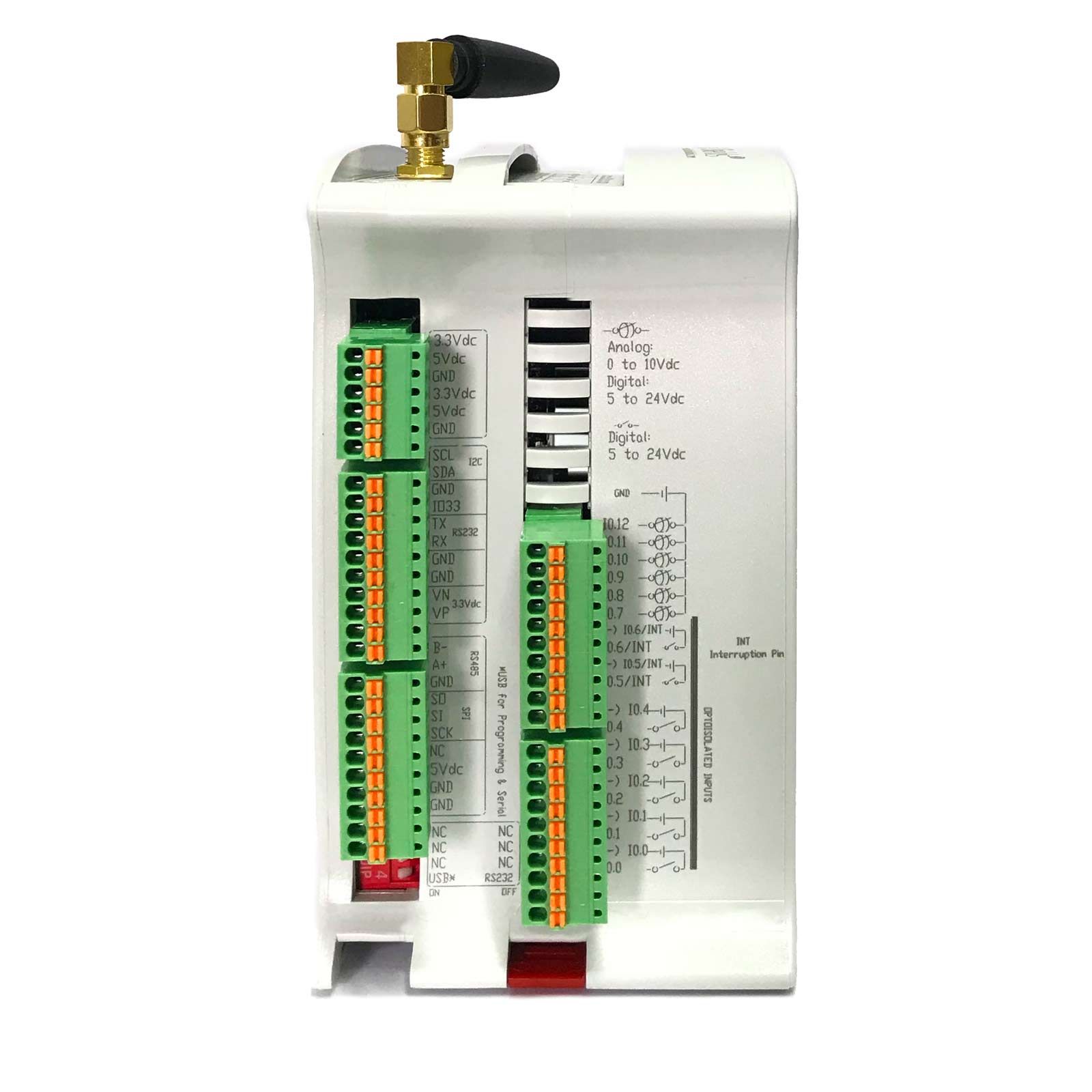
Industrial Shields ESP32-based PLCs have an external SPI port, which connects to VSPI (SPI3).
As for the pins you use and the switch configuration for your ESP32 industrial PLC: no switch configuration is required to use SPI communication. The following SPI pins are directly available on the PLC:
| Function | PLC Pin | ESP32 Pin |
| MISO | SO | GPIO 19 |
| MOSI | SI | GPIO 23 |
| CLOCK | SCK | GPIO 18 |
As you can see, there is no pin directly assigned to be the slave select. Any of the dedicated I/O pins available on the PLC can be used as the slave select, such as GPIO pin 0. The slave select pin will have to be configured manually, as can be seen in the software section of this tutorial.
Note: Internally, ESP32-based PLCs use the same SPI bus (SPI3) for the Ethernet connection, the µSD card and the external SPI.
Software
Make sure you have the industrialshields-esp-32 board package correctly installed in your Arduino IDE.
Software configuration
First of all, it is necessary to include the SPI.h library provided on our boards. Our SPI communication library is based on the Arduino SPI library, which allows SPI communication using ESP32 based PLCs. Note that the library only allows SPI communication acting as a master, it does not support slave mode.
This library can be included in this way:
#include <SPI.h>
To configure and use the slave select pin, you will need to configure it as an output and set its value as required. This can be done with the following functions:
pinMode(slaveSelectPin, OUTPUT);
digitalwrite(slaveSelectPin, LOW);
digitalWrite(slaveSelectPin, HIGH);
Basic Master example
This example shows how to send a message using SPI, in this case the character '0', and print the response via the serial port. Note that the SS pin needs to be configured manually, as it is not done by the library:
// Include the SPI library:
#include <SPI.h>
// Set pin as the slave select:
const int slaveSelectPin = GPIO_0;
volatile byte receivedData;
void setup() {
  Serial.begin(9600);
  // Set the slaveSelectPin as an output:
  pinMode(slaveSelectPin, OUTPUT);
  // Initialize SPI:
  SPI.begin();
}
void loop() {
  SPI.beginTransaction(SPISettings(100000, MSBFIRST, SPI_MODE0));
  digitalWrite(slaveSelectPin, LOW); // Start of transmission: set chip select LOW
  receivedData = SPI.transfer('0');
  digitalWrite(slaveSelectPin, HIGH); // End of transmission: set chip select HIGH
  SPI.endTransaction();
  Serial.println((char)receivedData);
  delay(100);
}

In summary, the SPI communication protocol is an important aspect of industrial automation and is widely used for communication between microcontrollers and peripheral devices. With its full-duplex, synchronous and serial communication characteristics, it enables efficient data transfer between devices.
How to use SPI on an ESP32 based PLC