

Introduction
The aim of this post is to show how easy it is to communicate controllers using the Modbus protocol without the need of additional libraries.
As a continuation of Part 1, in Part 2, the ESP32 will act as the master controller, and the M-Duino industrial PLC will be the slave, just the opposite of Part 1. Part 2 is focused on the master PLC, the slave controller will use the Industrial Shields libraries to simplify the explanation.
For more information about how to program the slave controller without extra libraries, check Part 1.
Requirements


Connection between industrial controllers
To connect them properly, you will need a pair of twisted pair cables. Using the Half Duplex configuration on the M-Duino PLC, connect both wires to RS485 B- and A+. These two wires must be connected to the RS485 pins of ESP32s as well, like so:
M-Duino PLC pin B- to ESP32 PLC pin B-
M-Duino PLC pin A+ to M-Duino PLC pin A+
Remember that to work with RS485 and ESP32 PLC you will need to configure its switches. Turning off the third switch will enable RS485 communication. Check the serigraphy of the PLC if you have any doubts.
M-Duino code
In this case the M-Duino will be the slave controller, so to implement its program just open the Arduino IDE and go to File -> Examples -> Modbus -> ModbusRTUSlave. (You can find the Modbus repository here).
The only modification needed here is to change this line:
for this one:
This will set the RS485 communication to have 8 data bits, no parity and 1 stop bit.
Also, the code uses M-Duino 21+ mapping. If having any other model, change the definition of the array digitalOutputsPins to match all your digital outputs. For example, for M-Duino 58+ PLC, the array should be like this:
The other arrays will not be used, so it makes no sense to modify them.
This code will check for Modbus requests and update its digital and analogue outputs depending on the messages received automatically. Upload the code to your M-Duino PLC using the Industrial Shields boards, and let's jump into the ESP32 code.
ESP32 code
As seen in Part 1, the Modbus request ADU message is like so
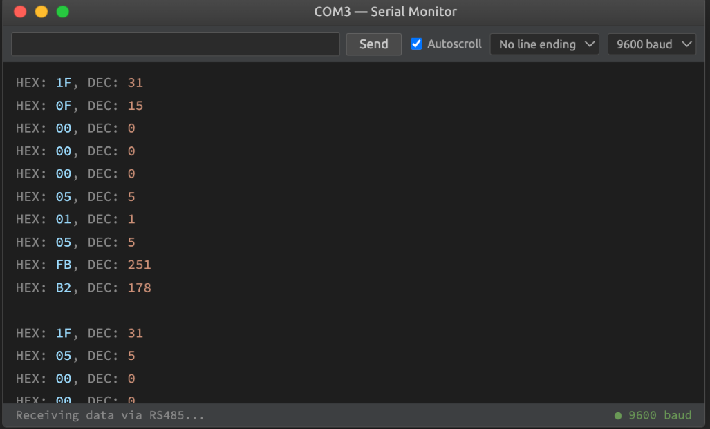
To send ADUs like in the image above, you can use the following example. Following the structure from Part 1, two possible request messages can be done: writeSimpleCoil or writeMulipleCoils.
First, 3 global variables are initialised. Then, Serial and RS485 objects begin with their respective baudrates. The RS485 baudrate must be the same as in the M-Duino code, and also the parity (SERIAL_8N1). As this parity is the default, it is not necessary to specify it.
After the setup() function, there is the crc16() function. This function is used to calculate the CRC redundancy for the entire message of the request. Because the CRC redundancy can be calculated using different algorithms, it is important to make the same operations as the slave open source based controller.
Then, Then, the functions are defined, the purpose of which is to carry out the corresponding request. Each of them has the same size as those seen in part Part 1 (writeSingleCoil() with an 8 bytes size and writeMultipleCoils() with a size of 10 bytes, and have the same utility as those implemented in the ModbusRTUMaster library. Finally, there is the sendRequest() function that sends the corresponding request to the RS485 port.
In the loop() function, a request is done every second. It can be either writeSingleCoil() or writeMultipleCoils(), depending on the value within the second "if" conditional.
On the one hand, if that conditional is true, then writeSingleCoil is chosen. With this, every second a new digital output will be turned on for a total of num outputs. As in our case an M-Duino 58+ PLC is used, the total number is 14, so one loop will be 14 seconds in total, one for each digital output.
Change that value to adjust your total numbers of digital outputs if you have any other model. Once a loop is done, the coilValue will toggle and then repeat the sequence but turning off all outputs. This sequence will repeat infinitely.
On the other hand, if the conditional value is false, then writeMultipleCoils is selected. In this case, an array of random numbers is generated and then a request is made, asking the slave controller to trigger all digital outputs, depending on the value of each element of the array.
For an array like the following: { 1 , 0 , 1 , 1 , 0 }, digital outputs number 0, 2 and 3 will turn on and outputs 1 and 4 will turn off. Remember to change the value of num, depending on the number of digital outputs of your PLC for industrial automation.

Conclusions
In these two posts, you have learned how requests are made in Modbus protocol communication to understand the simplest and most straightforward Modbus applications, but this is just the beginning.
After reading Part 1 and Part 2, you are now ready to jump into using more complex Modbus libraries and use the protocol to its full potential!