Introduction
Data exchange between controllers is very important to easily control a system, and using the Modbus protocol is one of the best solutions.
The Modbus RTU protocol is used worldwide in many areas, such as automation and industry, and is very useful in master-slave systems.
If you are interested in how Modbus works, see the following post for an in-depth understanding of the protocol. This post will explain the communication between a M-Duino PLC as master and the ESP32 PLC as slave.
Requirements
Connection between industrial PLCs
You will need a pair of twisted wires to connect both controllers. Using Half Duplex configuration on the M-Duino PLC, connect both wires to RS485 pins B- and A+ pins. These two wires must be connected to the RS485 pins of the ESP32 as well, like this:
M-Duino PLC pin B- to ESP32 PLC pin B-
M-Duino PLC pin A+ to M-Duino PLC pin A+
Remember: You will need to configure the switches to work with RS485 and ESP32 PLC . Turning off the third switch will enable RS485 communication.
Check the serigraphy of the PLC if having any doubt.
M-Duino code
As the M-Duino based PLC will act as a master, you need to program it to make requests every few seconds. The program will make two types of requests: Write Single Coil or Write Multiple Coils.
Before uploading the code, install the Industrial Shields boards for Arduino IDE and change the board to your M-Duino PLC model. Remember also to install the Modbus library here.
/*
    Copyright (c) 2018 Boot&Work Corp., S.L. All rights reserved
    This program is free software: you can redistribute it and/or modify
    it under the terms of the GNU Lesser General Public License as published by
    the Free Software Foundation, either version 3 of the License, or
    (at your option) any later version.
    This program is distributed in the hope that it will be useful,
    but WITHOUT ANY WARRANTY; without even the implied warranty of
    MERCHANTABILITY or FITNESS FOR A PARTICULAR PURPOSE. See the
    GNU Lesser General Public License for more details.
    You should have received a copy of the GNU Lesser General Public License
    along with this program. If not, see <http://www.gnu.org/licenses/>.
*/

#include <ModbusRTUMaster.h>
#include <RS485.h>
ModbusRTUMaster master(RS485);
uint32_t lastSentTime = 0UL;
const uint32_t baudrate = 38400UL;
//////////////////////////////////////////////////////////////////////////
void setup() {
    Serial.begin(9600);
    RS485.begin(baudrate, HALFDUPLEX, SERIAL_8E1);

    master.begin(baudrate);
}
//////////////////////////////////////////////////////////////////////////
void loop() {
    if (millis() - lastSentTime > 1500) {
        if (random() & 0x01) {
            bool values[5];
            for (int i = 0; i < 5; i++) {
                values[i] = random() & 0x01;
            }
            if (!master.writeMultipleCoils(31, 0, values, 5)) {
                // Failure treatment
                Serial.println("Request failed");
            }
        }
        else {
            if (!master.writeSingleCoil(31, 0, random() & 0x01)) {
                // Failure treatment
                Serial.println("Request failed");
            }
        }
        lastSentTime = millis();
    }
    // Check available responses often
    if (master.isWaitingResponse()) {
        ModbusResponse response = master.available();
        if (response) {
            if (response.hasError()) {
                // Response failure treatment. You can use response.getErrorCode()
                // to get the error code.
                Serial.print("Error ");
                Serial.println(response.getErrorCode());
            } else {
                // Get the discrete inputs values from the response
                if (response.hasError()) {
                    // Response failure treatment. You can use response.getErrorCode()
                    // to get the error code.
                    Serial.print("Error ");
                    Serial.println(response.getErrorCode());
                } else {
                    Serial.println("Done");
                }
            }
        }
    }
}
Let's focus our attention on the loop function. Every 1.5 seconds, there is a 50% chance the program sends a writeMultipleCoils() request or a writeSingleCoil() one.
On the one hand, if a writeMultipleCoils() is chosen, it first creates an array with 5 random values, one for each digital output of the slave controller. Then the request is made with the slave address (31), the first coil to write (addres 0), the array and the number of outputs to trigger.
On the other hand, if a writeSingleCoil() is chosen, it makes a request with the slave address number (31), the coil to write (address 0) and the value to write (0 or 1).
ESP32 code
Before getting into the ESP32 code, let's use a simple code to see what is the M-Duino PLC (master) sending.
First, change the board to your ESP32 PLC model in the Arduino IDE. Then, go to File -> Examples -> RS485 -> Receive. Upload it and open the Serial Monitor. If you have programmed the M-Duino PLC correctly, it will look something like this:
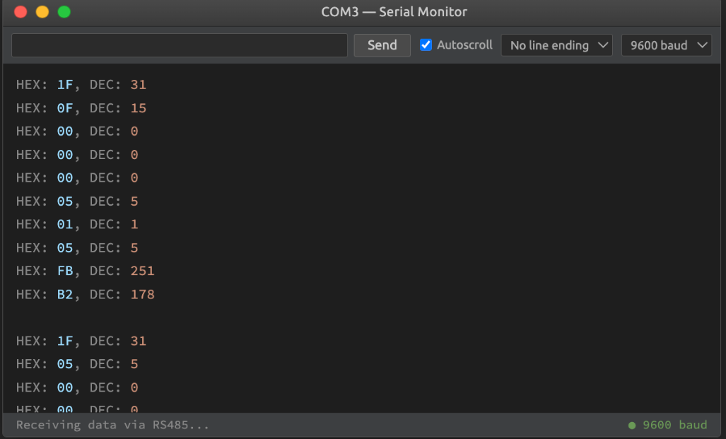
This is a Modbus ADU (Application Data Unit). The first byte shows the slave address, 31 (0x1F) in the example, and the second tells us what type of request the master is trying to do, writeMultipleCoils (0x0F) in this case.
Then 2 bytes are used to tell the first address to write to (0x0000 in this case). The next two shows how many outputs the master is trying to write to (0x0005).
The next one (0x01) gives you the byte count, and the following tells you what to write at every coil (0x05). 0x05 in binary is 00000101, so only output 0 and 2 will be turned on (bits number 0 and 2 are set to 1). The last 2 bytes are for the crc redundancy.
Now that you know what every byte is for in a Modbus ADU, let's get into the code. Notice that no extra libraries have been used, as you only have 2 types of requests and it is very easy to implement the functions:
/*
    Copyright (c) 2018 Boot&Work Corp., S.L. All rights reserved
    This program is free software: you can redistribute it and/or modify
    it under the terms of the GNU Lesser General Public License as published by
    the Free Software Foundation, either version 3 of the License, or
    (at your option) any later version.
    This program is distributed in the hope that it will be useful,
    but WITHOUT ANY WARRANTY; without even the implied warranty of
    MERCHANTABILITY or FITNESS FOR A PARTICULAR PURPOSE. See the
    GNU Lesser General Public License for more details.
    You should have received a copy of the GNU Lesser General Public License
    along with this program. If not, see <http://www.gnu.org/licenses/>.
*/

#include <RS485.h>
const int slave_address = 31;
int relayOutputsPins[] = {
    R0_4, R0_5, R0_6, R0_7, R0_8,
};
//////////////////////////////////////////////////////////////////////////
void setup() {
    Serial.begin(9600);
    RS485.begin(38400);
}
//////////////////////////////////////////////////////////////////////////
void doWriteMultipleCoils(uint8_t total_pins, uint8_t values) {
    // turn on relays
    for (int i = 0; i < total_pins; i++) {
        (values & (1<<i)) ? digitalWrite(relayOutputsPins[i], HIGH) : digitalWrite(relayOutputsPins[i], LOW);
    }
}
//////////////////////////////////////////////////////////////////////////
void doWriteSingleCoil(uint8_t value) {
    // turn on digital output
    if (value == 255) {
        digitalWrite(Q0_0, HIGH);
        digitalWrite(Q0_1, LOW);
    }
    else {
        digitalWrite(Q0_0, LOW);
        digitalWrite(Q0_1, HIGH);
    }
}
//////////////////////////////////////////////////////////////////////////
void readModbus(uint8_t aux[]) {
    int b = 0;
    int max_bits;
    while (1) {
        if (RS485.available()) {
            byte rx = RS485.read();
            aux[b] = rx;
            if (b == 1) max_bits = (rx == 0x05) ? 8 : 10;
            if (++b == max_bits) break;
        }
    }
}
//////////////////////////////////////////////////////////////////////////
void loop() {
    uint8_t aux[10];
    readModbus(aux);
    if (aux[0] == slave_address) {
        if (aux[1] == 0x05) doWriteSingleCoil(aux[4]);
        else if (aux[1] == 0x0F) doWriteMultipleCoils(aux[5], aux[7]);
    }
    else Serial.println("Bad slave address");
}
First, define the slave address, 31, just like in the master code. After that, define all 5 output pins you want to trigger. An ESP32 38R PLC was used in the example, but maybe your PLC model does not any have relay outputs, so take that into consideration and change the array to match your output pins.
In the setup function Serial and RS485 are started with their own baudrates (both the baudrates of the Modbus object of the M-Duino PLC, and the RS485 of the ESP32 must be the same).). Having said that, let's jump straight into the loop function.
There, you call the readModbus() function which will get all the Modbus ADUs from the master and store them in the array called aux. It already identifies between 8 byte ADUs (writeSingleCoil()) and 10 byte ADUs (writeMultipleCoils()).
Then, all that is left is to differentiate between Single and Multiple writes and call the proper function with the necessary parameters.
If you want to implement ,ore types of Modbus requests, simply check the function code for that request and add an "else if (aux[1] == function code)" below the last one and create another function to do the job, following the structure of the already created functions. To implement a read request, remember that you will need to send some data back to the master controller.
And that's all!
In this post you have learned how Modbus ADU works and how easy it is to process requests and act accordingly without the need for external libraries.
Now it is time to review Part 2 to learn the opposite case, ESP32 PLC as master and M-Duino PLC as slave.