
Introduction
The devices of the ESP32 PLC family have a defined number of digital outputs. All of them can be programmed as PWM outputs, if required. As we know, the PWM (Pulse Width Modulation) is a kind of voltage signal used to send information or to modify the amount of power sent for each charge. So, in this blog, you are going to see how to configure PWM outputs.
Requirements
Code Explanation
Apart from the Adafruit_PWMServoDriver, you must include the Wire.h I2C library to manage the IOs so they are connected to the ESP32 through I2C Expansion Chips:
#include <Wire.h>
#include <Adafruit_PWMServoDriver.h>
You must vinculate each PWM object per I2C chip address:
Adafruit_PWMServoDriver pwm1 = Adafruit_PWMServoDriver(0x40);
Adafruit_PWMServoDriver pwm2 = Adafruit_PWMServoDriver(0x41);
In the setup() block you have to begin each PWM object and set each frequence taking into account that the maxiumum allowed is 1600Hz.
void setup() {
  Serial.begin(9600);
  Serial.println("PWM test!");

  pwm1.begin();
  pwm1.setPWMFreq(1600);  // This is the maximum PWM frequency -> 1600Hz

  pwm2.begin();
  pwm2.setPWMFreq(1600);  // This is the maximum PWM frequency -> 1600Hz
}
After all the commented setup, then you can use the PWM function to enable the outputs as you desire, considering the pointed fields:
pwmObjectName.setPWM(output, 4095-part cycle ON, 4095-part cycle OFF);
Take into account that the all the digital outputs of the PLC can be used as PWM and you can reference in the code through 2 different nomenclatures:
- Serigraphy nomenclature. Ex:
pwm1.setPWM(Q0_0, 4096, 0);
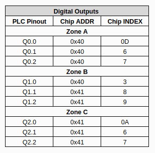
- I2C Chip Index (considering that every PWM object is linked to each I2C Chip Address). You can have a look at the IOs equivalence table that you can find below and also on the UserGuide. Ex:
pwm1.setPWM(11, 4096, 0);
This example is based on ESP32 PLC 42+ so it enables and disables all its PWM outputs for 2 seconds each state:
void loop() {
  // put your main code here, to run repeatedly:
  pwm1.setPWM(Q0_0, 4096, 0); //0x40, 11
  pwm1.setPWM(Q0_1, 4096, 0); //0x40, 10
  pwm1.setPWM(Q0_2, 4096, 0); //0x40, 9
  pwm1.setPWM(Q0_3, 4096, 0); //0x40, 8
  pwm1.setPWM(Q0_4, 4096, 0); //0x40, 12
  pwm1.setPWM(Q0_5, 4096, 0); //0x40, 13
  pwm1.setPWM(Q0_6, 4096, 0); //0x40, 6
  pwm1.setPWM(Q0_7, 4096, 0); //0x40, 7

  pwm1.setPWM(Q1_0, 4096, 0); //0x40, 15
  pwm1.setPWM(Q1_1, 4096, 0); //0x40, 14
  pwm1.setPWM(Q1_2, 4096, 0); //0x40, 0
  pwm1.setPWM(Q1_3, 4096, 0); //0x40, 1
  pwm1.setPWM(Q1_4, 4096, 0); //0x40, 2
  pwm1.setPWM(Q1_5, 4096, 0); //0x40, 3
  pwm2.setPWM(Q1_6, 4096, 0); //0x41, 8
  pwm2.setPWM(Q1_7, 4096, 0); //0x41, 9
  delay(2000);

  pwm1.setPWM(Q0_0, 0, 4096); //0x40, 11
  pwm1.setPWM(Q0_1, 0, 4096); //0x40, 10
  pwm1.setPWM(  pwm1.setPWM(Q0_4, 0, 4096); //0x40, 12
  pwm1.setPWM(Q0_5, 0, 4096); //0x40, 13
  pwm1.setPWM(Q0_6, 0, 4096); //0x40, 6
  pwm1.setPWM(Q0_7, 0, 4096); //0x40, 7

  pwm1.setPWM(Q1_0, 0, 4096); //0x40, 15
  pwm1.setPWM(Q1_1, 0, 4096); //0x40, 14
  pwm1.setPWM(Q1_2, 0, 4096); //0x40, 0
  pwm1.setPWM(Q1_3, 0, 4096); //0x40, 1
  pwm1.setPWM(Q1_4, 0, 4096); //0x40, 2
  pwm1.setPWM(Q1_5, 0, 4096); //0x40, 3
  pwm2.setPWM(Q1_6, 0, 4096); //0x41, 8
  pwm2.setPWM(Q1_7, 0, 4096); //0x41, 9

  delay(2000);
}  pwm1.setPWM(Q0_4, 0, 4096); //0x40, 12
  pwm1.setPWM(Q0_5, 0, 4096); //0x40, 13
  pwm1.setPWM(Q0_6, 0, 4096); //0x40, 6
  pwm1.setPWM(Q0_7, 0, 4096); //0x40, 7

  pwm1.setPWM(Q1_0, 0, 4096); //0x40, 15
  pwm1.setPWM(Q1_1, 0, 4096); //0x40, 14
  pwm1.setPWM(Q1_2, 0, 4096); //0x40, 0
  pwm1.setPWM(Q1_3, 0, 4096); //0x40, 1
  pwm1.setPWM(Q1_4, 0, 4096); //0x40, 2
  pwm1.setPWM(Q1_5, 0, 4096); //0x40, 3
  pwm2.setPWM(Q1_6, 0, 4096); //0x41, 8
  pwm2.setPWM(Q1_7, 0, 4096); //0x41, 9

  delay(2000);
}
-Analog-Digital Outputs:

-Analog-Digital-Relay Outputs:
Remember that you can modify some parameters of the library (considering the hardware boundaries) to fit your application requierements:
Adrafruit-PWM-Servo-Driver-Library
Complete Code
#include <Wire.h>
#include <Adafruit_PWMServoDriver.h>

Adafruit_PWMServoDriver pwm1 = Adafruit_PWMServoDriver(0x40);
Adafruit_PWMServoDriver pwm2 = Adafruit_PWMServoDriver(0x41);

void setup() {
  Serial.begin(9600);
  Serial.println("PWM test!");

  pwm1.begin();
  pwm1.setPWMFreq(1600);  // This is the maximum PWM frequency -> 1600Hz

  pwm2.begin();
  pwm2.setPWMFreq(1600);  // This is the maximum PWM frequency -> 1600Hz
}

void loop() {
  // put your main code here, to run repeatedly:
  pwm1.setPWM(Q0_0, 4096, 0); //0x40, 11
  pwm1.setPWM(Q0_1, 4096, 0); //0x40, 10
  pwm1.setPWM(Q0_2, 4096, 0); //0x40, 9
  pwm1.setPWM(Q0_3, 4096, 0); //0x40, 8
  pwm1.setPWM(Q0_4, 4096, 0); //0x40, 12
  pwm1.setPWM(Q0_5, 4096, 0); //0x40, 13
  pwm1.setPWM(Q0_6, 4096, 0); //0x40, 6
  pwm1.setPWM(Q0_7, 4096, 0); //0x40, 7

  pwm1.setPWM(Q1_0, 4096, 0); //0x40, 15
  pwm1.setPWM(Q1_1, 4096, 0); //0x40, 14
  pwm1.setPWM(Q1_2, 4096, 0); //0x40, 0
  pwm1.setPWM(Q1_3, 4096, 0); //0x40, 1
  pwm1.setPWM(Q1_4, 4096, 0); //0x40, 2
  pwm1.setPWM(Q1_5, 4096, 0); //0x40, 3
  pwm2.setPWM(Q1_6, 4096, 0); //0x41, 8
  pwm2.setPWM(Q1_7, 4096, 0); //0x41, 9

  delay(2000);

  pwm1.setPWM(Q0_0, 0, 4096); //0x40, 11
  pwm1.setPWM(Q0_1, 0, 4096); //0x40, 10
  pwm1.setPWM(Q0_2, 0, 4096); //0x40, 9
  pwm1.setPWM(Q0_3, 0, 4096); //0x40, 8
  pwm1.setPWM(Q0_4, 0, 4096); //0x40, 12
  pwm1.setPWM(Q0_5, 0, 4096); //0x40, 13
  pwm1.setPWM(Q0_6, 0, 4096); //0x40, 6
  pwm1.setPWM(Q0_7, 0, 4096); //0x40, 7

  pwm1.setPWM(Q1_0, 0, 4096); //0x40, 15
  pwm1.setPWM(Q1_1, 0, 4096); //0x40, 14
  pwm1.setPWM(Q1_2, 0, 4096); //0x40, 0
  pwm1.setPWM(Q1_3, 0, 4096); //0x40, 1
  pwm1.setPWM(Q1_4, 0, 4096); //0x40, 2
  pwm1.setPWM(Q1_5, 0, 4096); //0x40, 3
  pwm2.setPWM(Q1_6, 0, 4096); //0x41, 8
  pwm2.setPWM(Q1_7, 0, 4096); //0x41, 9

  delay(2000);
}