Introduction
In this post, we will examine the time response characteristics of the various pin types of the Weidos-MKR1010-A1 Programmable Logic Controller. We will see aspects like the maximum switching frequency and the rising or falling times, which are crucial for functions such as interacting with external peripherals.
Requirements
If you want to measure the PLC characteristics, you will also need a precise oscilloscope capable of reading at the 100ns scale.
Technical specifications
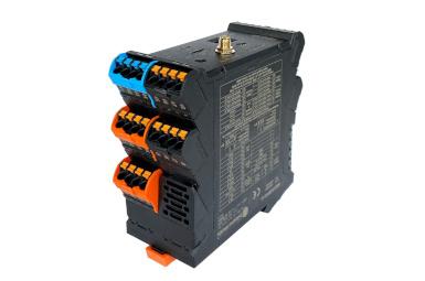
The PLC WEIDOS-MKR1010-A1 features 36 pins dedicated to various purposes, and we will now analyze some of them. Among all its pins, 4 are allocated for digital inputs (25-28), and 4 for analog inputs (15-18), which can also be used as digital inputs. It has 4 digital outputs (55-58) and one analog output (45). Finally, we will also assess the 2 multifunction pins (41-42) available on the PLC.
The digital input pins operate with a voltage of 5 or higher for HIGH values and 3.3 or lower for LOW values. Digital output pins provide a maximum voltage of the supply voltage minus 1V. Analog input pins work within the range of 0 to 10V. Analog output pins deliver a range of 0 to 10V. Multifunction pins operate based on the microswitch configuration at either 3.3V or 5V.
For more information, please refer to the documentation here.
Data collection
Below, all the extracted data is presented. It's important to remember that these data are approximations obtained in the laboratory, implying that it is very likely that your device, if it is the same, has similar or identical times. Nevertheless, later on, an explanation will be provided on how these data have been obtained.
Signal transition time
Output (pin n.º)
| Rise time
| Fall time
| Signal frequency - Maximum
Stable
| Signal frequency - Maximum
|
| Digital (55) | 770 - 900 ns | 20 µs | 704.2 Hz | - |
| Analog (45) | 60 ms | 70 ms | 2.5 Hz | 6.6 Hz |
| Multifunction (41) | 600 - 900 ns | 1.6 µs | 25 Hz | 50 Hz |
Response time
Input type (pin n.º)
| Output type (pin n.º) | Internal measurement (Script)
| External measurement (Osc.)
|
Digital (25)
| Digital (56) | 706 µs | 706 µs |
Digital (25)
| Analog (45)
| 6 µs | 75 ms
|
Analog (15)
| Digital (56)
| 1.55 ms | - |
Analog (15)
| Analog (45)
| 859 µs | - |
Sampling time
Input type (pin n.º)
| Sampling frequency - Average
| Sampling frequency - Highest read time
|
Digital input (25)
| 346 KHz (2.98 µs) | 83.33 KHz (12 µs) |
Analog input (15)
| 1.167 KHz (856.5 μs) | 1.15 KHz (870μs) |
Analog input (used as digital) (15)
| 333.33 KHz (3 µs)
| 83.33 KHz (12 µs) |
Multifunctional digital input (41) | 225.73 KHz (4.43 µs) | 71.43 KHz (14 µs) |
Multifunctional analog input (41) | 113.9 KHz (8.78 µs) | 55.55 KHz (18 µs) |
Output type (pin n.º)
| Sampling frequency - Average
| Sampling frequency - Highest read time
|
Digital output (55)
| 1.42 KHz (704.3 µs) | 71.43 KHz (714 μs) |
Analog output (45)
| 225.73 KHz (4.43 µs) | 71.43 KHz (14 µs) |
Multifunctional digital output (41)
| 224.72 KHz (4.45 µs) | 71.43 KHz (14 µs) |
Multifunctional analog output (41)
| 114.15 KHz (8.76 µs) | 55.55 KHz (18 µs) |
Pin Evaluation: Performance and Timing Analysis
Signal transition time
The time it takes for a signal to transition from low to high is called the rise time, and the time it takes to transition from high to low is called the fall time. These times are measured from 10% to 90% of the total signal amplitude. They are crucial in electronic systems to ensure fast transitions and meet specific timing requirements.
- Required Tools: Oscilloscope.
- Procedure:
- Connect the oscilloscope to the pin you want to measure.
- Generate a square wave of a known frequency and connect it to the same pin.
- Observe the waveform on the oscilloscope and measure the rise/fall time (the time it takes to transition from one state to another).
- The maximum frequency the pin can handle can be determined by observing when the waveform begins to distort or lose its square shape.
Digital Outputs
Using both the oscilloscope and the code, you can visualize state changes on pin 55 and measure transition times. The results are as follows:
- Rise time: 770 - 900 ns
- Fall time. 20 µs
Also, by minimizing the delay between value changes, a signal with a maximum frequency of 704.2 Hz is achieved.
void setup() {}void loop(){ digitalWrite(pin55,HIGH);
//delay(1000);
digitalWrite(pin55,LOW);
//delay(1000);
}
Analog Outputs
Using both the oscilloscope and the code, you can visualize state changes on pin 45 and measure transition times. The results are as follows:
- Rise time: 60 ms
- Fall time. 70 ms
Also, by minimizing the delay between value changes, a signal with a maximum frequency of 2.5 Hz is achieved.
void setup() {}void loop(){ analogWrite(pin45, 1023);
delay(1000);
analogWrite(pin45, 0);
delay(1000);
}
Multifunction Outputs
Using both the oscilloscope and the code, you can visualize state changes on pin 41 and measure transition times. The results are as follows:
- Rise time: 600 - 900 ns
- Fall time. 1.6 µs
Also, by minimizing the delay between value changes, a signal with a maximum frequency of 25 Hz is achieved.
void setup() {}void loop(){ analogWrite(pin41, 1023);
delay(20);
analogWrite(pin41, 0);
delay(20);
}
Response Time
"Response time" in electronics refers to the time it takes for a system to react to a change in input conditions. It is crucial in circuits and devices to measure how quickly they respond to signals or stimuli. A low response time is generally preferable, but in some cases, a controlled delay may be needed.
- Required Tools: Oscilloscope.
- Procedure:
- Apply a change in the logic level of the pin of interest (e.g., from LOW to HIGH or vice versa).
- Observe the waveform on the oscilloscope and measure the time it takes to reach a specific level.
- This response time may depend on factors such as the pin's load capacity and the microcontroller's speed.
Digital - Digital
Generating a pulse equivalent to HIGH and connecting it to pin 25 through the code we have created, as shown below, we observe the response through pin 56 in 706 µs.
unsigned long t1, t2;
void setup() { Serial.begin(115200);
delay(1000);
}
void loop() { digitalWrite(pin55, HIGH);
t1 = micros();
if (digitalRead(pin25) == HIGH) { digitalWrite(pin56, HIGH);
} else { digitalWrite(pin56, LOW);
}
t2 = micros();
delay(1000);
digitalWrite(pin55, LOW);
Serial.print("Digital Pin Value: "); Serial.println((float)t2-(float)t1);
delay(1000);
}
It is important to note that the code measures the reaction time that the PLC takes to respond to the stimulus. It does not include the time it takes for the signal to establish itself, meaning the rise and fall times should be observed with an oscilloscope. In this case, the result has been 706 µs.
Digital - Analog
Generating a pulse equivalent to HIGH and connecting it to pin 25 through the code we have created, as shown below, we observe the response through pin 45 in 6 µs.
unsigned long t1, t2;
void setup() { Serial.begin(115200);
delay(1000);
}
void loop() { digitalWrite(pin55, HIGH);
t1 = micros();
  if (digitalRead(pin25) == LOW) {
    analogWrite(pin45, 1023);
  } else {
    analogWrite(pin45, 0);
  }
  t2 = micros();
delay(1000);
digitalWrite(pin55, LOW);
Serial.print("Pin Value: "); Serial.println((float)t2-(float)t1);
delay(1000);
}
It is important to note that the code measures the reaction time that the PLC takes to respond to the stimulus. It does not include the time it takes for the signal to establish itself, meaning the rise and fall times should be observed with an oscilloscope. In this case, the result has been 75 ms.
Analog - Digital
Generating a pulse equivalent to
1023 and connecting it to
pin 15 through the code we have created, as shown below, we observe the response through
pin 56 in
1.55 ms.
unsigned long t1, t2;

void setup() {
  Serial.begin(115200);
  delay(1000);
}

void loop() {
  digitalWrite(pin55, HIGH);
  t1 = micros();
  if (analogRead(pin15) < 200) {
    digitalWrite(pin56, HIGH);
  } else {
    digitalWrite(pin56, HIGH);
  }
  t2 = micros();

  delay(1000);
  digitalWrite(pin55, LOW);

  Serial.print("Digital Pin Value: ");
  Serial.println(t2-t1);
  delay(1000);
}
It is important to note that the code measures the reaction time that the PLC takes to respond to the stimulus. It does not include the time it takes for the signal to establish itself, meaning the rise and fall times should be observed with an oscilloscope.
Analog - Analog
Generating a pulse equivalent to 1023 and connecting it to pin 15 through the code we have created, as shown below, we observe the response through pin 45 in 859 µs.
unsigned long t1, t2;

void setup() {
  Serial.begin(115200);
  delay(1000);
}

void loop() {
  digitalWrite(pin55, HIGH);
  t1 = micros();

  if (analogRead(pin15)< 200) {
    analogWrite(pin45, 512);
  } else {
    analogWrite(pin45, 1023);
  }
  t2 = micros();

  delay(1000);
  digitalWrite(pin55, LOW);

  Serial.print("Pin Value: ");
  Serial.println(t2-t1);
  delay(1000);
}
It is important to note that the code measures the reaction time that the PLC takes to respond to the stimulus. It does not include the time it takes for the signal to establish itself, meaning the rise and fall times should be observed with an oscilloscope.
Sampling time
Sampling time is the period between consecutive measurements when converting a continuous analog signal into a discrete digital signal. It plays a crucial role in maintaining the fidelity of the signal during the conversion process.
- Required Tools: No specific instrument needed, but you can use the microcontroller's timing functions.
- Procedure:
- To measure sampling time, you can use the timing functions of the Arduino microcontroller.
- Set up a timer to generate interrupts at a known frequency.
- In the interrupt routine, perform a sampling operation on the pin of interest.
- Measure the time between consecutive samples to determine the sampling time.
Here is a code that simplifies the task of measuring both the average and maximum sampling time of the digital, analog, and multifunction pins of the PLC. In this code, the variable N_TIMES indicates the number of times the check will be performed. The higher the value, the more reliable the results will be; it is recommended to set values close to 10.000, as with this number of checks, we believe it is sufficient to obtain sufficiently precise values.
#define N_TIMES 10000

unsigned long t1, t2, t_max, t_average;

void setup() {
  Serial.begin(115200);
  while (!Serial);
  Serial.println("============================");
  Serial.println("=  SAMPLING TIME ANALYSIS  =");
  Serial.println("============================");
  Serial.println("Wait, this process may take some time ... (all data is in micro-seconds)");
  Serial.println();

  // Digital IN
  t_max = 0;
  t_average = 0;

  for (long i = 0; i<N_TIMES; i++) {
    t1 = micros();
    digitalRead(pin25);
    t2 = micros();
    t_average += (t2-t1);
    if (t_max < t2-t1) t_max = t2-t1;
  }

  Serial.println("1/9 - Digital input (pin25)");
  Serial.print("      Max time: ");
  Serial.println(t_max);
  Serial.print("      Average time: ");
  Serial.println(t_average/(float)N_TIMES);

  // Analog IN
  t_max = 0;
  t_average = 0;

  for (long i = 0; i<N_TIMES; i++) {
    t1 = micros();
    analogRead(pin15);
    t2 = micros();
    t_average += (t2-t1);
    if (t_max < t2-t1) t_max = t2-t1;
  }

  Serial.println("2/9 - Analog input(pin15)");
  Serial.print("      Max time: ");
  Serial.println(t_max);
  Serial.print("      Average time: ");
  Serial.println(t_average/(float)N_TIMES);

  // Analog as Digital IN
  t_max = 0;
  t_average = 0;

  for (long i = 0; i<N_TIMES; i++) {
    t1 = micros();
    digitalRead(pin15);
    t2 = micros();
    t_average += (t2-t1);
    if (t_max < t2-t1) t_max = t2-t1;
  }

  Serial.println("3/9 - Analog as Digital input (pin15)");
  Serial.print("      Max time: ");
  Serial.println(t_max);
  Serial.print("      Average time: ");
  Serial.println(t_average/(float)N_TIMES);

  // Multifunction D. IN
  t_max = 0;
  t_average = 0;

  for (long i = 0; i<N_TIMES; i++) {
    t1 = micros();
    digitalWrite(pin41,HIGH); // Digital
    t2 = micros();
    t_average += (t2-t1);
    if (t_max < t2-t1) t_max = t2-t1;
  }
  Serial.println("4/9 - Multifunctional D. input(pin41)");
  Serial.print("      Max time: ");
  Serial.println(t_max);
  Serial.print("      Average time: ");
  Serial.println(t_average/(float)N_TIMES);

  // Multifunction A. IN
  t_max = 0;
  t_average = 0;

  for (long i = 0; i<N_TIMES; i++) {
    t1 = micros();
    analogWrite(pin41,1023); // Analogic
    t2 = micros();
    t_average += (t2-t1);
    if (t_max < t2-t1) t_max = t2-t1;
  }
  Serial.println("5/9 - Multifunctional A. input (pin41)");
  Serial.print("      Max time: ");
  Serial.println(t_max);
  Serial.print("      Average time: ");
  Serial.println(t_average/(float)N_TIMES);

  // Digital OUT
  t_max = 0;
  t_average = 0;
  for (long i = 0; i<N_TIMES; i++) {
    t1 = micros();
    digitalWrite(pin55,HIGH);
    t2 = micros();
    t_average += (t2-t1);
    if (t_max < t2-t1) t_max = t2-t1;
  }
  Serial.println("6/9 - Digital output (pin55)");
  Serial.print("      Max time: ");
  Serial.println(t_max);
  Serial.print("      Average time: ");
  Serial.println(t_average/(float)N_TIMES);

  // Analog OUT
  t_max = 0;
  t_average = 0;
  for (long i = 0; i<N_TIMES; i++) {
    t1 = micros();
    analogWrite(pin45,1023);
    t2 = micros();
    t_average += (t2-t1);
    if (t_max < t2-t1) t_max = t2-t1;
  }
  Serial.println("7/9 - Analog output (pin45)");
  Serial.print("      Max time: ");
  Serial.println(t_max);
  Serial.print("      Average time: ");
  Serial.println(t_average/(float)N_TIMES);

  // Multifunction D. OUT
  t_max = 0;
  t_average = 0;

  for (long i = 0; i<N_TIMES; i++) {
    t1 = micros();
    digitalWrite(pin41,HIGH); // Digital
    t2 = micros();
    t_average += (t2-t1);
    if (t_max < t2-t1) t_max = t2-t1;
  }
  Serial.println("8/9 - Multifunctional Digital output(pin41)");
  Serial.print("      Max time: ");
  Serial.println(t_max);
  Serial.print("      Average time: ");
  Serial.println(t_average/(float)N_TIMES);

  // Multifunction A. IN
  t_max = 0;
  t_average = 0;

  for (long i = 0; i<N_TIMES; i++) {
    t1 = micros();
    analogWrite(pin41,1023); // Analogic
    t2 = micros();
    t_average += (t2-t1);
    if (t_max < t2-t1) t_max = t2-t1;
  }
  Serial.println("9/9 - Multifunctional Analog output (pin41)");
  Serial.print("      Max time: ");
  Serial.println(t_max);
  Serial.print("      Average time: ");
  Serial.println(t_average/(float)N_TIMES);
}

void loop() {}
This code will output all sampling data through the serial port (Console log). Remember to configure your Integrated Development Environment (IDE) correctly, with the corresponding board or PLC.