
The Industrial Shields ESP32 PLC includes Wi-Fi 802.11 b/g/n and dual-mode Bluetooth 4.2 (Classic BR/EDR and BLE) built directly into the ESP32 chip. No additional wireless modules are required. This article covers the main connectivity specifications of the ESP32 and provides working examples for WiFi network scanning and BLE communication programmed with the Arduino IDE.
ESP32 WiFi and Bluetooth specifications
The ESP32 is a 2.4 GHz single-chip solution combining Wi-Fi and Bluetooth, manufactured using TSMC's 40 nm low-power technology. It integrates a dual-core Xtensa LX6 processor, 520 KB of SRAM, and hardware cryptographic accelerators, making it suitable for connected industrial applications. The full specification is available in the official datasheet:
ESP32 Series Datasheet (Espressif)
WiFi
- 802.11 b/g/n (2.4 GHz), up to 150 Mbps in 802.11n mode
- Station, SoftAP, and combined SoftAP + Station mode
- WPA/WPA2/WPA2-Enterprise and WPS support
Bluetooth and BLE
- Bluetooth 4.2 BR/EDR and BLE dual-mode controller
- +12 dBm transmit power
- BLE receive sensitivity of -97 dBm
CPU and memory
- Dual-core Xtensa 32-bit LX6 at up to 240 MHz (up to 600 MIPS)
- 520 KB SRAM, 448 KB ROM
- 16 KB SRAM in RTC for deep-sleep wake-up
- Multiple power modes including deep sleep with ULP coprocessor
Peripheral interfaces
- 34 programmable GPIOs
- 12-bit ADC up to 18 channels, 2x 8-bit DAC, 10 touch sensors
- 4x SPI, 2x I2C, 2x I2S, 3x UART, CAN 2.0
- LED PWM up to 16 channels, motor PWM
- Ethernet MAC with IEEE 1588 precision time protocol support
- Hardware security: secure boot, flash encryption, AES, SHA-2, RSA, RNG
The diagram below shows the standard ESP32 chip pinout for reference:

Setting up Arduino IDE for the ESP32 PLC
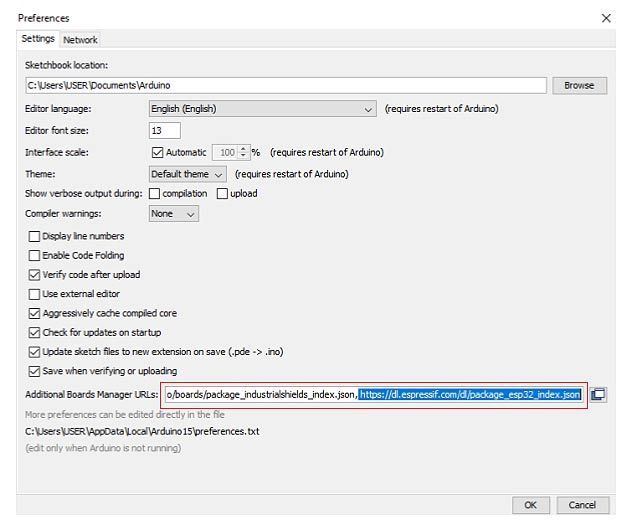
To program an Industrial Shields ESP32 PLC you need to install the IS-specific board package in the Arduino IDE. It provides the correct pin aliases (Q0_0, Q0_1, I0_0, etc.) and hardware definitions for each ESP32 PLC model. Go to File > Preferences and add the following URL in Additional boards manager URLs:
https://apps.industrialshields.com/main/arduino/boards/package_industrialshields_esp32_index.json
If you already have another URL in that field, separate them with a comma.
Go to Tools > Board > Boards Manager, search for "Industrial Shields ESP32" and install the package. Once installed, go to Tools > Board and select your ESP32 PLC model.

WiFi example: network scanner
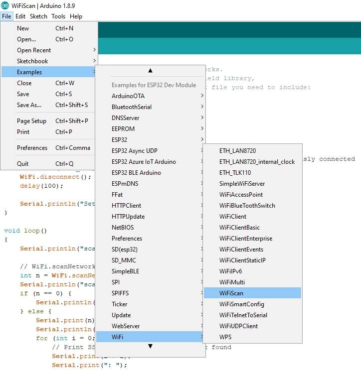
The following sketch scans for available WiFi networks every 5 seconds and prints the SSID, signal strength (RSSI), and encryption status of each to the serial monitor. It uses Serial2, which is the available serial port on IS ESP32 PLC models.
Open it from File > Examples > Examples for your ESP32 PLC model > WiFi > WiFiScan, or use the code below:
#include "WiFi.h"

void setup()
{
    Serial2.begin(19200);
    WiFi.mode(WIFI_STA);
    WiFi.disconnect();
    delay(100);
    Serial2.println("Setup done");
}

void loop()
{
    int start = millis();
    Serial2.println("scan start");

    int n = WiFi.scanNetworks();
    int finish = millis();
    Serial2.print("scan done, time = ");
    Serial2.print(finish - start);
    Serial2.println(" ms");
    if (n == 0) {
        Serial2.println("no networks found");
    } else {
        Serial2.print(n);
        Serial2.println(" networks found");
        for (int i = 0; i < n; ++i) {
            Serial2.print(i + 1);
            Serial2.print(": ");
            Serial2.print(WiFi.SSID(i));
            Serial2.print(" (");
            Serial2.print(WiFi.RSSI(i));
            Serial2.print(")");
            Serial2.println((WiFi.encryptionType(i) == WIFI_AUTH_OPEN) ? " " : "*");
            delay(10);
        }
    }
    delay(5000);
}
Uploading the sketch
To upload a sketch to the ESP32 PLC, hold the BOOT button while the IDE starts the upload. Once complete, press the EN button to run the program. After a successful upload, the serial monitor will display the scan results:

BLE example: writing to a characteristic
The following sketch creates a BLE server on the ESP32 PLC with a custom service and characteristic. A BLE scanner app on a smartphone (such as nRF Connect or LightBlue) can connect to the device and write a string value to the characteristic. The ESP32 PLC then prints the received value to the serial monitor.
Each BLE service and characteristic requires a UUID (universally unique identifier). Generate your own 128-bit UUIDs and replace the example values in the sketch:

/*
    Based on Neil Kolban's example for IDF:
    https://github.com/nkolban/esp32-snippets/blob/master/cpp_utils/tests/BLE%20Tests/SampleWrite.cpp
    Ported to Arduino ESP32 by Evandro Copercini
*/

#include <BLEDevice.h>
#include <BLEUtils.h>
#include <BLEServer.h>

#define SERVICE_UUID        "3e3593cf-e5cb-46ee-8fa4-16c8b6a563d0" // Replace with your own UUID
#define CHARACTERISTIC_UUID "beb5483e-36e1-4688-b7f5-ea07361b26a8" // Replace with your own UUID

class MyCallbacks: public BLECharacteristicCallbacks {
    void onWrite(BLECharacteristic *pCharacteristic) {
      std::string value = pCharacteristic->getValue();
      if (value.length() > 0) {
        Serial2.println("*********");
        Serial2.print("New value: ");
        for (int i = 0; i < value.length(); i++)
          Serial2.print(value[i]);
        Serial2.println();
        Serial2.println("*********");
      }
    }
};

void setup() {
  Serial2.begin(19200);
  Serial2.println("1- Download a BLE scanner app to your phone (e.g. nRF Connect)");
  Serial2.println("2- Scan for BLE devices");
  Serial2.println("3- Connect to MyESP32");
  Serial2.println("4- Go to CUSTOM CHARACTERISTIC and write something");
  Serial2.println("5- See the result in this monitor");

  BLEDevice::init("MyESP32");
  BLEServer *pServer = BLEDevice::createServer();
  BLEService *pService = pServer->createService(SERVICE_UUID);
  BLECharacteristic *pCharacteristic = pService->createCharacteristic(
    CHARACTERISTIC_UUID,
    BLECharacteristic::PROPERTY_READ | BLECharacteristic::PROPERTY_WRITE
  );
  pCharacteristic->setCallbacks(new MyCallbacks());
  pCharacteristic->setValue("Hello World");
  pService->start();
  BLEAdvertising *pAdvertising = pServer->getAdvertising();
  pAdvertising->start();
}

void loop() {
  delay(2000);
}
Once the sketch is running, the serial monitor shows five steps. After following them from your phone, any value you write to the characteristic will appear in the monitor:
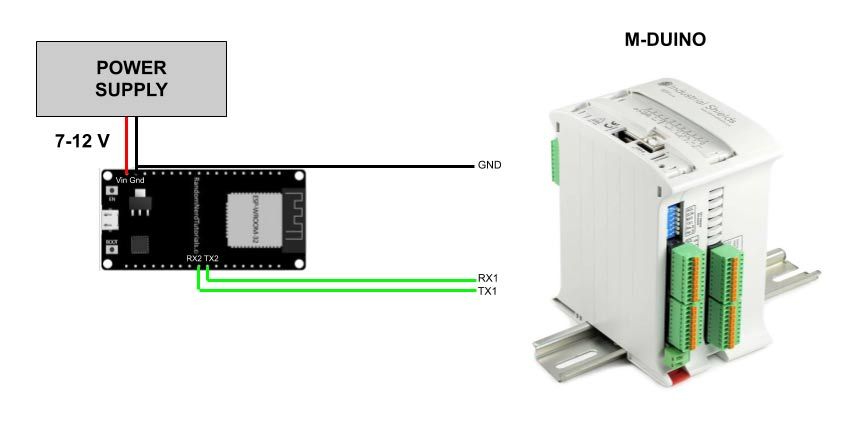
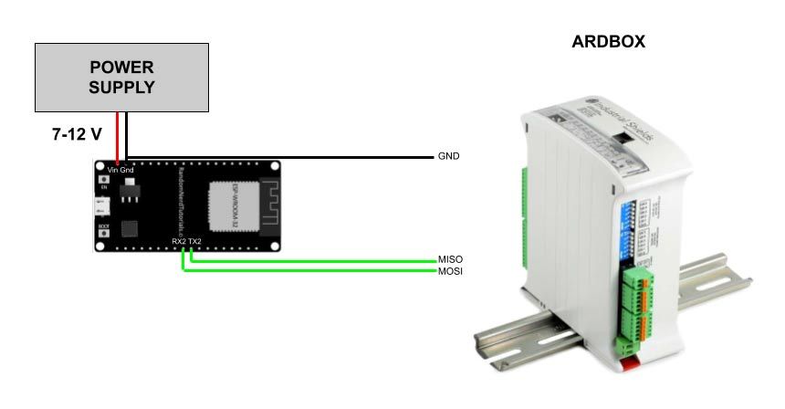
Using the ESP32 PLC as a wireless gateway for M-Duino or Ardbox
An ESP32 PLC can act as a WiFi or BLE gateway for an Arduino-based PLC (M-Duino or Ardbox) that does not have built-in wireless connectivity. The two devices communicate over TTL serial at 19200 baud. The ESP32 PLC sends and receives data wirelessly and forwards it to the Arduino PLC over serial.
Remember to connect the GND of both devices.
Connection with M-Duino
The ESP32 PLC uses Serial2 (TX2/RX2 pins). Connect ESP32 TX2 to M-Duino RX1 and ESP32 RX2 to M-Duino TX1. Power the ESP32 PLC from the same 24 V supply as the M-Duino.
The M-Duino sketch reads data received on Serial1 and prints to Serial:
void setup() {
  Serial.begin(19200);
  Serial1.begin(19200);
}

void loop() {
  if (Serial1.available()) {
    Serial.print((char)Serial1.read());
  }
}
Connection with Ardbox
On the Ardbox, the hardware Serial0 (pins 0 and 1) is reserved for RS232. Use SoftwareSerial instead, with MISO as RX and MOSI as TX.
#include <SoftwareSerial.h>

SoftwareSerial mySerial(MISO, MOSI); // RX, TX

void setup() {
  Serial.begin(19200);
  mySerial.begin(19200);
}

void loop() {
  if (mySerial.available()) {
    Serial.print((char)mySerial.read());
  }
}
For the full range of Industrial Shields PLCs based on Arduino, Raspberry Pi, and ESP32, visit the ESP32 PLC product page.