Index
This post will be explained how the module ESP32 works according to the ESP32 Series Datasheet. At the end of the post, there is a practical example.
Here you have a link to the Datasheet:
Overview
ESP32 is a single 2.4 GHz Wi-Fi and Bluetooth combo chip designed with the TSMC ultra-low-power 40 nm technology. It is designed to achieve the best power and RF performance, showing robustness, versatility, and reliability in a wide variety of applications and power scenarios. Some applications are Generic Low-power IoT Sensor Hub, Generic Low-power IoT Data Loggers and Mesh Network.
It is designed for mobile, wearable electronics, and Internet-of-Things (IoT) applications. It features all the state-of-the-art characteristics of low-power chips, including fine-grained clock gating, multiple power modes, and dynamic power scaling. The power amplifier's output is also adjustable, thus contributing to an optimal trade-off between communication range, data rate, and power consumption.
General Features of the ESP32
ESP32 Wi-Fi
- 802.11 b/g/n
- 802.11 n (2.4 GHz), up to 150 Mbps
ESP32 Bluetooth / ESP32 BLE
- Bluetooth 4.2 BR/EDR BLE dual-mode controller
- +12 dBm transmitting power
- NZIF receiver with -97 dBm BLE sensivity
CPU and Memory
- Xtensa single-/dual-core 32-bit LX6 microprocessor(s), up to 600 MIPS (200 MIPS for ESP32-S0WD, 400 MIPS for ESP32-D2WD)
- 448 KB ROM
- 520 KB SRAM
- 16 KB SRAM in RTC ( 8KB RTC FAST Memory accessed by the main CPU during RTC Boot from the Deep-sleep mode and 8 KB RTC SLOW Memory accessed by the co-processor during the Deep-sleep mode).
Clocks and timers
- Internal 8 MHz oscillators with calibration
- Internal RC oscillator with calibration
- External 2 MHz ~ 60 MHz crystal oscillator (40 MHz only for Wi-Fi/BT functionality)
- External 32 kHz crystal oscillator for RTC with calibration
- Two timer groups, including 2 x 64-bit timers and 1 x main watchdog in each group
- One RTC timer
- RTC watchdog
Advanced Peripheral Interfaces
- 34 x programmable GPIOs
- 12-bit SAR ADC up to 18 channels
- 2 x 8-bit DAC
- 10 x touch sensors
- 4 x SPI
- 2 x I2S
- 2 x I2C
- 3 x UART
- 1 host (SD/eMMC/SDIO)
- 1 slave (SDIO/SP)
- Ethernet MAC interface with dedicated DMA and IEEE 1588 support
- CAN 2.0
- IR (TX(RX)
- Motor PWM
- LED PWM up to 16 channels
- Hall sensor
Security
- Secure boot
- Flash encryption
- 1024-bit OTP, up to 768-bit for customers
- Cryptographic hardware acceleration:
- AES
- Hash (SHA-2)
- RSA
- EXX
- Random Number Generator (RNG)
The image below shows the ESP32 pinout:
For more information see Datasheet.
ESP32 Arduino
ESP32 board
To load the program into the ESP32 you have to install the board. Go to File > Preferences and into Additional Boards Manager URLs add the next URL: https://dl.espressif.com/dl/package_esp32_index.json
*If you already have one URL put it next to the other separated by a comma, like in the image below.
Now, you can install the board. Go to Tools > Boards > Boards Manager and search by ESP32. Will appear the ESP32 by Espressif Systems. Install it.
Once it is installed go to Tools > Boards and choose DOIT ESP32 DEVKIT V1.
Examples
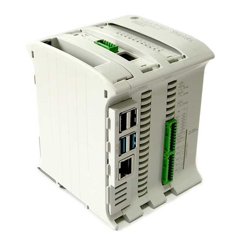
Moreover, there are multiple applications for multiple sectors to get industrial control. With ESP32 projects for automation solutions.
ESP32 WiFi
You will find some examples to test in File > Examples > Examples for ESP32 Dev Module. Let's take a look at the WiFi Scan example.
Here you have the code with some additions and comments:
ESP32 WiFi > Wifi_Scan code:
#include "WiFi.h"void setup()
{
Serial2.begin(19200);
// Set WiFi to station mode and disconnect from an AP if it was previously connected
WiFi.mode(WIFI_STA);
WiFi.disconnect();
delay(100);
Serial2.println("Setup done");
} void loop()
{
int start = millis(); // Capture start time
Serial2.println("scan start"); // WiFi.scanNetworks will return the number of networks found
int n = WiFi.scanNetworks();
int finish = millis();
Serial2.print("scan done, time = ");
Serial2.print(finish - start);
Serial2.println(" ms");
if (n == 0) {
Serial2.println("no networks found");
} else {
Serial2.print(n);
Serial2.println(" networks found");
for (int i = 0; i < n; ++i) {
// Print SSID and RSSI for each network found
Serial2.print(i + 1);
Serial2.print(": ");
Serial2.print(WiFi.SSID(i));
Serial2.print(" (");
Serial2.print(WiFi.RSSI(i));
Serial2.print(")");
Serial2.println((WiFi.encryptionType(i) == WIFI_AUTH_OPEN)?" ":"*");
delay(10);
}
}
Serial2.print(""); // Wait a bit before scanning again
delay(5000);
}
Load a program
IMPORTANT
To load a program, you have to press the button BOOT while is uploading the program. Once it is uploaded, press the button EN to run the program.
Result
After uploading the previous program of WiFiScan, you will see something like this in the Serial Monitor:
ESP32 Bluetooth
You will find some examples to test in File > Examples > Examples for ESP32 Dev Module. Let's take a look at the BLE to write an example.
Here, you have the code with some additions and comments:
ESP32 BLE > BLE write code:
/*Based on Neil Kolban example for IDF: https://github.com/nkolban/esp32-snippets/blob/master/cpp_utils/tests/BLE%20Tests/SampleWrite.cpp
Ported to Arduino ESP32 by Evandro Copercini
*/ #include <BLEDevice.h>
#include <BLEUtils.h>
#include <BLEServer.h> // See the following for generating UUIDs:
// https://www.uuidgenerator.net/ #define SERVICE_UUID "3e3593cf-e5cb-46ee-8fa4-16c8b6a563d0" // example comes with 4fafc201-1fb5-459e-8fcc-c5c9c331914b
#define CHARACTERISTIC_UUID "beb5483e-36e1-4688-b7f5-ea07361b26a8" class MyCallbacks: public BLECharacteristicCallbacks {
void onWrite(BLECharacteristic *pCharacteristic) {
std::string value = pCharacteristic->getValue(); if (value.length() > 0) {
Serial2.println("*********");
Serial2.print("New value: ");
for (int i = 0; i < value.length(); i++)
Serial2.print(value[i]); Serial2.println();
Serial2.println("*********");
}
}
}; void setup() {
Serial2.begin(19200); Serial2.println("1- Download and install an BLE scanner app in your phone");
Serial2.println("2- Scan for BLE devices in the app");
Serial2.println("3- Connect to MyESP32");
Serial2.println("4- Go to CUSTOM CHARACTERISTIC in CUSTOM SERVICE and write something");
Serial2.println("5- See the magic =)"); BLEDevice::init("MyESP32");
BLEServer *pServer = BLEDevice::createServer(); BLEService *pService = pServer->createService(SERVICE_UUID); BLECharacteristic *pCharacteristic = pService->createCharacteristic(
CHARACTERISTIC_UUID,
BLECharacteristic::PROPERTY_READ |
BLECharacteristic::PROPERTY_WRITE
); pCharacteristic->setCallbacks(new MyCallbacks()); pCharacteristic->setValue("Hello World");
pService->start(); BLEAdvertising *pAdvertising = pServer->getAdvertising();
pAdvertising->start();
} void loop() {
// put your main code here, to run repeatedly:
delay(2000);
}
As you can see, you have to go to www.uuidgenerator.net to generate a 128-bit number identifier UUID (universally unique identifier). It is used to ensure that the services and characteristics of your device are globally unique.
Afterload, the program in the Serial Monitor you will see 5 steps to follow:
- Download and install a BLE scanner app on your phone. For example, BLE Scanner from Bluepixel Technologies.
- Scan for BLE devices in the app.
- Connect to MyESP32. You won't see it until you run the program.
- Go to CUSTOM CHARACTERISTIC in CUSTOM SERVICE and write something.
- See the magic =). Everything you write will be printed.
Result
After uploading the previous program of BLE write you will see something like this in the Serial Monitor.
Connections with our industrial PLC
M-Duino
The communication between the module WiFi and the PLC is by TTL. The ESP32 uses Serial2 to send the data to the PLC. The PLC receives the data by Serial1. So you have to connect the ESP TX2 pin to the PLC RX1 pin and the ESP RX2 pin to the PLC TX1 pin. The ESP connects the Vin and GND to the Power Supply to power. From now on, the Serial 1 communication will be busy.
Here you have a diagram:
Take a look at the M-Duino. The industrial PLC with Arduino MEGA
PLC code
The PLC program only reads the data received by Serial1 and prints it by Serial.
void setup() {
  Serial.begin(19200);
  Serial1.begin(19200);
}

void loop() {
  if (Serial1.available()){
    Serial.print((char)Serial1.read());
  }
}
To avoid disable communication pins RS232 (pins 0 and 1), we use Software Serial instead of Hardware Serial. In Ardbox, we have 3 pins RX available (MISO, MOSI and SCK). In this case, we use MISO as RX and MOSI as TX.
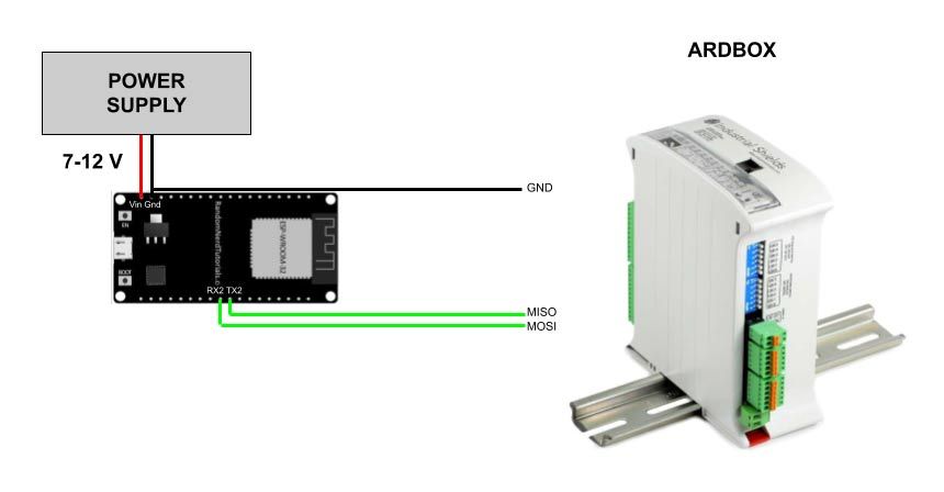
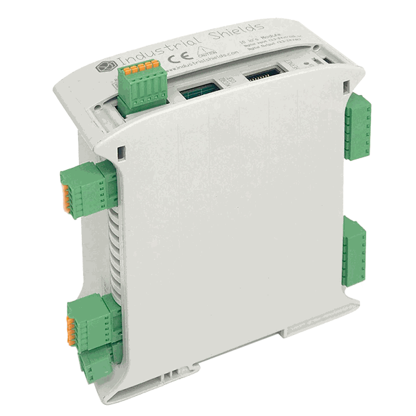
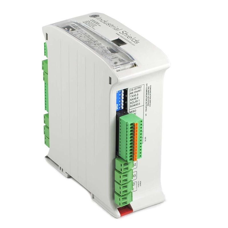
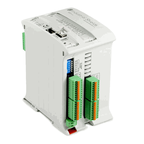
Take a look at the Ardbox. The industrial PLC with Arduino Leonardo.
Ardbox - Arduino PLC >>
PLC code
The function of the program is the same as before.
#include <SoftwareSerial.h>

SoftwareSerial mySerial(MISO, MOSI); // RX, TX

void setup() {
  Serial.begin(19200);
  mySerial.begin(19200);
}

void loop() {
  if (mySerial.available()){
    Serial.print((char)mySerial.read());
  }
}* To do the test, we made these connections, but the ESP32 module will be inside the PLC correctly connected.

ESP32 Bluetooth / BLE / WiFi