
Complete guide: Choosing an industrial controller
You can build a basic Arduino controller with 7 components: an Arduino Leonardo, three Proto Shield Rev3 boards with the optocoupler circuits for 9 isolated 24 V inputs, two Arduino 4 Relays Shields for 8 relay outputs, external connectors, cables and a plastic case. It takes about 5 hours of soldering and assembly. It is a good project to learn, but it has limits: the relays of the 4 Relays Shield are for loads up to 48 V (2 A at 30 Vdc per contact), the two shields use the same Arduino pins 4, 7, 8 and 12, so the 8 relays work as 4 pairs unless you rewire one shield, and the result has no DIN rail housing or CE declaration. For a machine, a ready-made PLC such as the Ardbox Relay, built around the same Arduino Leonardo, gives 10 inputs, 8 relays for 250 Vac 5 A / 30 Vdc 3 A, RS-485 and RS-232.
What you need: the 7 components
| Component | Quantity | What it does |
|---|---|---|
| Arduino Leonardo | 1 | The controller (ATmega32u4, 16 MHz, 32 KB flash, 2.5 KB SRAM) |
| Proto Shield Rev3 | 3 | Boards to solder the input circuits, 3 inputs on each one |
| Components for the isolated inputs | 9 inputs | One optocoupler circuit per 24 V input |
| Arduino 4 Relays Shield | 2 | 4 relays on each shield, 8 in total |
| External connectors | 17 | Terminals to wire the field signals |
| Development cables | 1 set | Connections between the boards |
| Plastic case | 1 | Housing for the stack of boards |
Use original boards: in a controller, the quality of the parts decides how long it works without faults.
How to assemble it
The relay shields already have the relays on the board: stack them on top of the Arduino Leonardo. The isolated inputs take more work, because you buy and solder every component. Each input uses an optocoupler: the 24 V field signal lights the LED of the optocoupler through a series resistor, and the transistor on the other side gives a logic signal to the Arduino pin, with no electrical connection between the two sides.
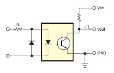
In our lab tests this simple circuit worked. For reasons of space, 3 Proto Shields are needed to solder the components of 9 inputs, 3 on each shield. External plug-in connectors make the wiring to the machine easier. Count about 5 hours to solder the components and stack the shields, depending on your soldering experience.
Check the pins before you stack the relay shields. The Arduino 4 Relays Shield drives its relays from pins 4, 7, 8 and 12. Two shields stacked without changes switch together in pairs. To get 8 independent relays, the control lines of the second shield must go to other free pins of the Leonardo.
DIY controller or Ardbox Relay: what is the difference?
| DIY controller | Ardbox Relay | |
|---|---|---|
| Controller | Arduino Leonardo | Arduino Leonardo (ATmega32u4) inside |
| Power supply | 5 Vdc from USB | 12 to 24 Vdc, with fuse and polarity protection |
| Inputs | 9 isolated, 24 Vdc | 10: 6 analog/digital (0 to 10 V) and 4 isolated digital (5 to 24 Vdc) |
| Relay outputs | 8 relays for loads up to 48 V, 2 A at 30 Vdc, driven as 4 pairs without rewiring | 8 independent relays, 250 Vac 5 A / 30 Vdc 3 A (resistive) |
| Other outputs | None | 2 analog/PWM (0 to 10 V) |
| Communications | TTL serial, I2C, SPI | RS-485, RS-232, TTL serial, I2C, SPI |
| Mounting | Plastic case | DIN rail, IP20, 100 x 45 x 115 mm |
| Certification | None for the assembled device | CE and UKCA certificates |
| Assembly time | About 5 hours | Ready to wire |
Both are programmed with the Arduino IDE, so a sketch written for the DIY controller is a good start for the Ardbox Arduino PLC, once you change the pin names.
When does a DIY controller make sense?
- Yes: to learn electronics and PLC logic, for a bench prototype, for a home project with low voltage loads.
- No: to switch mains voltage, in a machine that must have certified equipment, or where a stop costs money. There, use a DIN rail PLC with protected inputs and outputs and its certificates.
FAQ about building a PLC with Arduino
Can I build my own PLC with an Arduino?
Yes, a basic one: an Arduino Leonardo with isolated input circuits and relay shields gives 9 inputs and 8 relays. It works for learning and prototypes, but not as certified industrial equipment.
Can the Arduino 4 Relays Shield switch 230 Vac?
No. Arduino rates its relays for loads up to 48 V, with 2 A at 30 Vdc per contact. To switch 230 Vac, use relays rated for it, such as the 250 Vac 5 A relays of the Ardbox Relay.
Why do two stacked relay shields switch together?
Both shields use pins 4, 7, 8 and 12 of the Arduino. Without rewiring, relay 1 of both shields follows pin 4, and so on.
Can I program the controller in ladder logic?
With the Arduino IDE you write C++ sketches. For IEC 61131-3 languages such as ladder, see the OpenPLC guide for industrial PLCs.
Which Industrial Shields PLC is closest to this project?
The Ardbox Relay: it has the same Arduino Leonardo inside, 8 relays and 10 inputs in a 45 mm wide DIN rail housing.
Take it further
The ready-made alternative: a real project with an Ardbox Arduino PLC and the Ardbox Relay product page.
Case study
Three checks against bad parts. One small Ardbox Arduino PLC.
One of the checks reads a QR code with a reader on the RS-232 port and compares it with the reference.
Read the case study
Product
ARDBOX Relay, Arduino based PLC
A ready-made PLC for the DIN rail with relay outputs, instead of wiring and assembling your own parts.
See the product