
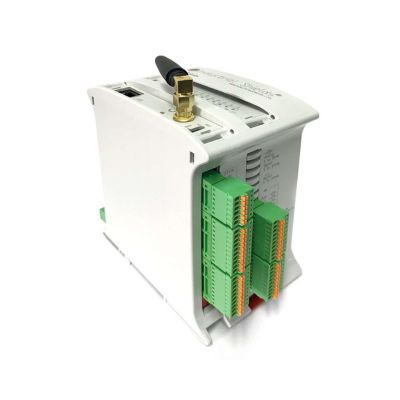
In this post we will see how to control a stepper motor using an ESP32 PLC. We will cover the basics of stepper motors, their features, and how they work in combination with a driver controlled by the PWM outputs of an ESP32 PLC. The motor and driver used are the 17HS16-2004S and the TB6600, respectively.
How stepper motors work
Stepper motors are electromechanical devices that convert electrical signals into precise mechanical movements. Unlike conventional motors that rotate continuously, stepper motors move in discrete steps. This makes them ideal for applications requiring accurate control over position, speed, and torque.
The discrete steps correspond to a fixed angular displacement known as the step angle, determined by the motor design and measured in degrees. Stepper motors can have different step angles, such as 1.8° (200 steps per revolution) or 0.9° (400 steps per revolution). The 17HS16-2004S uses 200 steps per revolution.
Three signals control a stepper motor: pulse, direction, and enable. The pulse signal determines the step frequency, the direction signal sets the rotation direction (clockwise or counterclockwise), and the enable signal activates or deactivates the motor. Controlling the timing and sequence of these signals allows precise positioning and rotation.
These signals cannot be sent directly to the motor; a driver is needed. The driver receives control signals from a controller such as a microcontroller or PLC and provides the necessary power and current to the motor coils. Stepper motor drivers offer features such as different control modes (full step, half step, microstep), current regulation, and protection mechanisms. The TB6600 used in this example supports up to 32 microsteps and can supply up to 4 A of current.
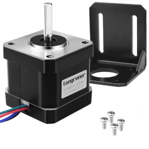
NEMA 17 17HS16-2004S motor specifications
The 17HS16-2004S NEMA 17 motor has the following electrical specifications:
| Electrical specification | |
|---|---|
| Bipolar/Unipolar | Bipolar |
| Holding torque | 0,45 Nm |
| Inductance | 2,6 mH |
| Phase resistance | 1,1 Ohm |
| Rated current | 2 A |
| Step angle | 1,8° |
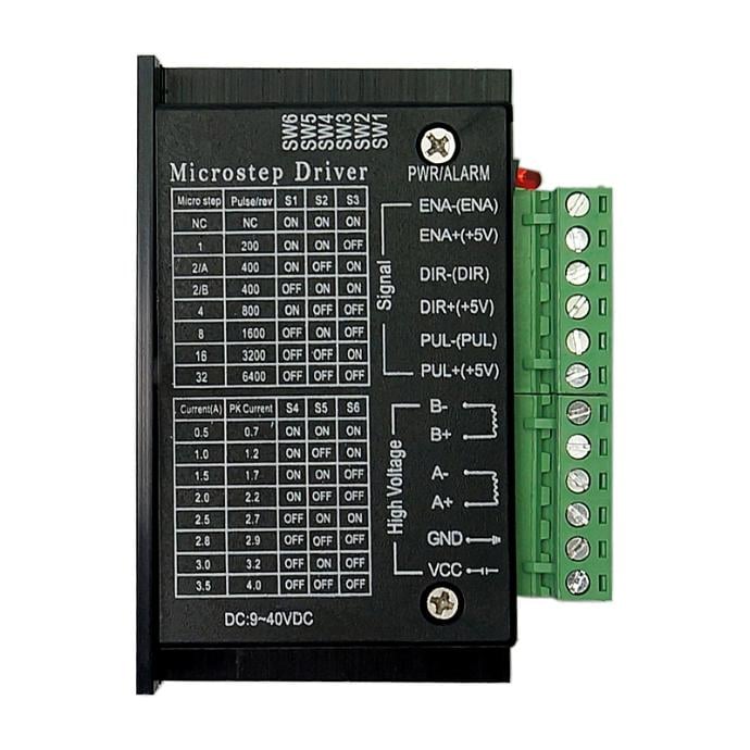
TB6600 microstep driver configuration
The TB6600 supports multiple modes depending on microstep and current settings:
- Microsteps: 1, 2, 4, 8, 16, 32
- Current (A): 0.5, 1.0, 1.5, 2.0, 2.5, 3.0, 3.5
To select the microsteps and current, the driver has 6 DIP switches. A table on the driver housing shows the correct on/off combination for each mode.
Wiring the ESP32 PLC to the TB6600 driver
The following connections are required to control the stepper motor from the ESP32 PLC.
Motor connections to the TB6600
- Blue --> A-
- Red --> A+
- Black --> B-
- Green --> B+
ESP32 PLC pin configuration
- Q0.0 --> PUL+
- Q0.1 --> DIR+
- Q0.2 --> ENA+
- GND --> PUL-, DIR-, ENA-
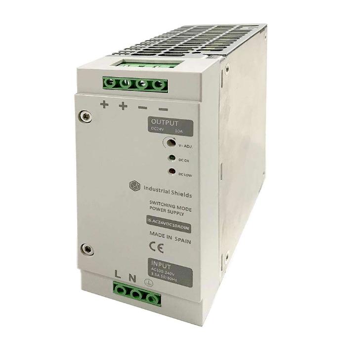
The ESP32 PLC outputs must be set to 5 V: connect QVdc to 5 V and COM(-) to GND. The same 12-24 V power supply can be used for both the ESP32 PLC and the TB6600.
Wiring diagram

Arduino sketches for the ESP32 PLC
To program the ESP32 PLC you need the Industrial Shields ESP32 package installed in the Arduino IDE. Both sketches require the Adafruit PWM Servo Driver library to generate the PWM signals.
Adafruit PWM Servo Driver Library
The ESP32 PLC PWM outputs support frequencies between 24 Hz and 1526 Hz, which limits the available motor speeds depending on the microstep configuration.
Constant speed movement
This sketch makes the motor perform movements at a constant speed.
First, define the physical setup: pins used, motor steps, and microstep configuration. In this example, Q0.0, Q0.1, and Q0.2 are used for the step, direction, and enable signals respectively, though any PWM output of the ESP32 PLC can be used. The STEPS_REV macro calculates the total steps per revolution based on the motor steps and driver microstep setting, which is useful for speed calculations.
The move_to() function takes a distance in revolutions, positive or negative depending on the desired direction, and calculates the time the motor must run at the target speed to cover that distance.
#include <Wire.h>
#include <Adafruit_PWMServoDriver.h>

#define DEBUG 1

#define STEP_PIN Q0_0
#define DIR_PIN Q0_1
#define ENA_PIN Q0_2

#define STEPS 200
#define MICROSTEPS 2
#define STEPS_REV (STEPS * MICROSTEPS)

Adafruit_PWMServoDriver pwm = Adafruit_PWMServoDriver(0x40);

float target_speed; // RPM

void setup_motor(void) {

  pinMode(STEP_PIN, OUTPUT);
  pinMode(DIR_PIN, OUTPUT);
  pinMode(ENA_PIN, OUTPUT);

  pwm.begin();
  pwm.setPWMFreq(1500);
  pwm.setPWM(STEP_PIN, 0, 2048);

  digitalWrite(ENA_PIN, HIGH);

}

void set_speed_rpm(float rpm) {

  pwm.setPWMFreq((uint16_t)((rpm/60)*STEPS_REV));

#if DEBUG
  Serial.print("set_speed_rmp: freq = ");
  Serial.println((uint16_t)((rpm/60)*STEPS_REV));
#endif

}

void move_to(float dist) {

  unsigned long init_time;
  unsigned long expected_time;

  expected_time = abs(dist)*1000*60./target_speed;

#if DEBUG
  Serial.print("move_to: expected_time = ");
  Serial.println(expected_time);
#endif

  set_speed_rpm(target_speed);

  digitalWrite(DIR_PIN, dist >= 0 ? HIGH : LOW);
  digitalWrite(ENA_PIN, LOW);
  init_time = millis();

  while ((millis() - init_time) <  expected_time);

  digitalWrite(ENA_PIN, HIGH);

#if DEBUG
  Serial.print("Time: ");
  Serial.println(millis() - init_time);
#endif

}

void setup() {

  Serial.begin(115200);
  setup_motor();

}

void loop() {

  target_speed = 50;
  move_to(1.45);
  delay(100);
  move_to(-1.45);
  delay(100);

}
Movement with acceleration
This sketch moves the motor applying acceleration and deceleration at the start and end of each movement.
Instead of calculating a fixed movement time, the program recalculates the travelled distance at fixed 30 ms intervals. The calculate_speed() function returns the speed the motor should rotate at at each moment, based on the acceleration and deceleration profiles computed at the start by calculate_accel(). This way the speed is adjusted every 30 ms. Depending on the acceleration value, the movement may not be perfectly smooth, since speed can vary significantly over 30 ms due to the update rate limit of the ESP32 PLC internal expansion chips.
Inside the main loop, the travelled distance is updated every 30 ms based on the current speed, allowing the program to track the motor position and perform fixed-distance moves.
#include <Wire.h>
#include <Adafruit_PWMServoDriver.h>

#define DEBUG 1

#define STEP_PIN Q0_0
#define DIR_PIN Q0_1
#define ENA_PIN Q0_2

#define STEPS 200
#define MICROSTEPS 2
#define STEPS_REV (STEPS * MICROSTEPS)
#define MIN_SPEED 24 // steps/s

Adafruit_PWMServoDriver pwm = Adafruit_PWMServoDriver(0x40);

float distance; // Voltes
float acceleration = 50000; // RPM^2
float target_speed; // RPM

void setup_motor(void) {

pinMode(STEP_PIN, OUTPUT);
pinMode(DIR_PIN, OUTPUT);
pinMode(ENA_PIN, OUTPUT);

pwm.begin();
pwm.setPWMFreq(1500);
pwm.setPWM(STEP_PIN, 0, 2048);

digitalWrite(ENA_PIN, HIGH);

}

void set_speed_rpm(float rpm) {

pwm.setPWMFreq((rpm/60)*STEPS_REV);

#if DEBUG
Serial.print("set_speed_rmp: freq = ");
Serial.println((rpm/60)*STEPS_REV);
#endif

}

float calculate_accel_dist(void) {

float acel_time = target_speed / acceleration;
float acel_dist = 0.5 * acceleration * pow(acel_time, 2);

if ( distance < (acel_dist * 2)) {
target_speed = sqrt( acceleration * distance );
acel_time = target_speed / acceleration ;
acel_dist = 0.5 * acceleration *pow(acel_time, 2);
}

return acel_dist;
}

float calculate_speed(float current_pos, float accel_dist) {

float speed = MIN_SPEED;
float accel_step = accel_dist * STEPS_REV;

if (current_pos <= accel_step) {
speed = sqrt(2 * (acceleration * STEPS_REV / 3600) * current_pos);
}
else if ((distance * STEPS_REV - current_pos ) <= (accel_step)) {
speed = sqrt(2 * (acceleration * STEPS_REV / 3600) * (distance * STEPS_REV - current_pos));
}
else {
speed = target_speed * STEPS_REV / 60;
}

if (speed < MIN_SPEED) speed = MIN_SPEED;

return speed;
}

void move_to(float dist) {

unsigned long init_time;
unsigned long current_time;

distance = abs(dist);

float accel_dist = calculate_accel_dist();
float time = 0;
float current_pos = 0;
float final_pos = distance * STEPS_REV;
float current_speed = 0;
float new_speed;
float time_delay = 30;

digitalWrite(DIR_PIN, dist >= 0 ? HIGH : LOW);
digitalWrite(ENA_PIN, LOW);
init_time = millis();

while (current_pos < final_pos) {
current_time = millis() - init_time;
new_speed = calculate_speed(current_pos, accel_dist);

if (new_speed != current_speed) {
set_speed_rpm(new_speed * 60 / STEPS_REV);
current_speed = new_speed;
}

delay(time_delay);
time += time_delay;
current_pos = current_pos + (current_speed * time_delay / 1000);
}

digitalWrite(ENA_PIN, HIGH);

}

void setup() {
Serial.begin(115200);
setup_motor();
}

void loop() {
target_speed = 100;
move_to(1);
delay(10);
move_to(-1);
delay(10);
}