Introduction
A Controller Area Network (CAN bus) is a robust vehicle bus standard designed to allow microcontrollers and devices to communicate with each other's applications without a host computer.
In this blog post, we are going to learn how to send and receive CAN bus messages from our Raspberry PLC.
What is CAN Bus?
CAN bus is a message-based protocol, designed originally for multiplex electrical wiring within automobiles to save on copper, but it can also be used in many other contexts. For each device, the data in a frame is transmitted sequentially but in such a way that if more than one device transmits at the same time, the highest priority device can continue while the others back off. Frames are received by all devices, including by the transmitting device.
Prior check
First of all, let's do a prior check to make sure that the setup is ready.
- Make sure your Rasberry PLCs are rightly connected to the power supply.
- Check that your Raspberry PLC has all the config files. Check >>
- Ensure that the SPI is enabled.
- Check that the /boot/config.txt file has the following line:
dtoverlay=mcp2515-can0,interrupt=5,oscillator=20000000
- Go to /etc/network/interfaces.d and check that the following can0 file exists and has this content in it:
auto can0
iface can0 inet manual
	pre-up /sbin/ip link set can0 type can bitrate 500000 triple-sampling on restart-ms 100
	up /sbin/ifconfig can0 up
down /sbin/ifconfig can0 down - Check that you can see the interface by doing:
ifconfig can0
- Make sure the can-utils library is properly installed. If it is not, then install it:
sudo apt update
sudo apt install can-utils
Connection
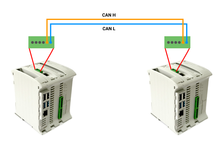
Now, it is time to connect the cables as shown in the picture below.

Testing
Once everything is ready to test the CAN Bus on our Raspberry PLC, we are going to follow these basic steps:
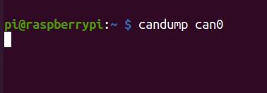
1. In order to wait for the data on the first Raspberry PLC, open up a terminal window and type the following:
candump can0

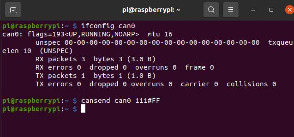
2. From the second Raspberry PLC, send the data with the following command:
cansend can0 111#FF

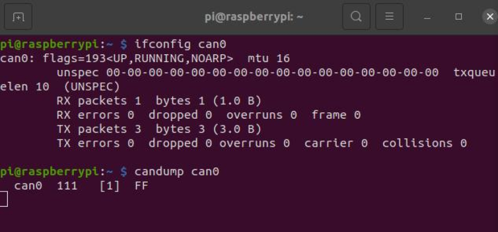
If everything went right, you will be able to see the message like in the picture below.
Now, enjoy the CAN Bus communication with this basic example for your Raspberry PLC!

How to test CANBUS with Raspberry PLC v3