
Introduction
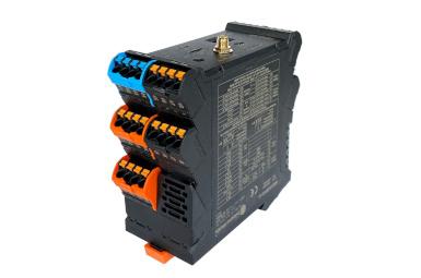
In this post, we will examine the time response characteristics of the various pin types of the Weidos-ESP32-A1 Programmable Logic Controller. We will see aspects like the maximum switching frequency and the rising or falling times, which are crucial for functions such as interacting with external peripherals.
Requirements
If you want to measure the PLC characteristics, you will also need a precise oscilloscope capable of reading at the 100ns scale.
Digital Outputs
The Weidos-ESP32-A1 has 4 digital outputs that work at the supply voltage (between 12 and 24V) minus 0.7V. The rise and fall times of the output when a level change is produced can be observed with an oscilloscope:
- Rise time: 1.02μs
- Fall time. 25μs
Using the digitalWrite() function, a signal with a maximum frequency of 640Hz can be achieved. This means that the update frequency of the outputs is the double, 1280Hz.
Digital Inputs
There are 4 digital inputs on the Weidos-ESP32-A1 PLC (plus the 4 analog inputs, which can also be used as digital). The inputs work at 24Vdc, interpreting every voltage higher than 5Vdc as a high value. We can use this program to measure the time it takes to perform a read operation using the digitalRead() function, computing the average and maximum time:
#define N_TIMES 100000
unsigned long t1, t2, t_max, t_average;
void setup() {Serial.begin(115200);
t_max = 0;
t_average = 0;
for (long i = 0; i<N_TIMES; i++) {t1 = micros();
digitalRead(pin25);
t2 = micros();
t_average += (t2-t1);
if (t_max < t2-t1) t_max = t2-t1;
}
Serial.print("Max time: ");Serial.println(t_max);
Serial.print("Average time: ");Serial.println(t_average/(float)N_TIMES);
}
The results are the following:
- Average sampling time: 0.92μs
- Maximum sampling time: 13μs
This average time means the maximum sampling frequency is 1.087MHz.
Analog Outputs
This PLC also includes 1 analog output with a 0-10Vdc output range and a 10 bits resolution DAC. In order to measure its capabilities we used this simple program to generate an output signal:
TaskHandle_t Task1;
void setup() {xTaskCreate(Task1code,"Task1",10000,NULL,25,&Task1);
}
void Task1code( void * parameter ){ for(;;){analogWrite(pin45, 1023);
delay(150);
analogWrite(pin45, 0);
delay(150);
}
}
The analog output, which corresponds to pin number 45 on the PLC, has the following characteristics:
- Rise time: 64.5ms
- Fall time: 79.5ms
With this results, we can output a signal of up to approximately 2.5Hz. Higher frequencies are too fast for the fall and rise time, and result in distorted signals.
Analog Inputs
The 4 analog inputs available in the PLC can be used as both analog and digital. When used as analog, the voltage range is 0-10V, and the value is converted to an integer with a 12 bit resolution ADC. When used as digital, it works as the digital only inputs, with a maximum input voltage of 24V.
The following code can be used to test both the analog and digital functions, changing the READ_TYPE directive.
TaskHandle_t Task1;
unsigned long t1, t2, t_max, t_average;

#define PIN pin15
#define READ_TYPE analogRead
#define N_AVERAGE 10000

void setup() {
  Serial.begin(115200);
  pinMode(PIN, INPUT);
  xTaskCreate(Task1code, "Task1", 10000, NULL, 25, &Task1);
}
void loop() {}

void Task1code( void * parameter ) {
  t_max = 0;
  t_average = 0;
  for (long i = 0; i < N_AVERAGE; i++) {
    t1 = micros();
    READ_TYPE(PIN);
    t2 = micros();
    t_average += (t2 - t1);
    if (t_max < t2 - t1) t_max = t2 - t1;
  }
  Serial.print("Max time: ");
  Serial.println(t_max);
  Serial.print("Average time: ");
  Serial.println(t_average / (float)N_AVERAGE);

  vTaskDelete(NULL);
}
The obtained results are the following. As it can be seen, the outputs can work faster as digital than as analog, but they are still slower than the only digital inputs.
Usage type | Average sampling time | Maximum sampling time |
Analog | 1000μs | 1770μs |
Digital | 453.9μs | 658μs |
Multifunction Pins
The Weidos-ESP32-A1 also has two multifunction pins. These pins are directly connected to the ESP32 pins, and can work as both digital input and output, and can also be used as interrupt in or PWM. Their operating voltage range is either 0-3.3V or 0-5V, selectable by a DIP switch in the PLC.
Used as a digital inputs, its characteristics are the following:
- Average sampling time: 0.81μs
- Maximum sampling time: 13μs
And when used as digital output these are its response times:
- Rise time: 2.80μs
- Fall time: 1.77μs
- Maximum output signal frequency: 23KHz
Summary
Inputs
Input type | Sampling frequency - Average | Sampling frequency - Highest read time |
Digital input | 1.087MHz (0.92μs) | 76.92KHz (13μs) |
Analog input | 1KHz (1000μs) | 564.97Hz (1770μs) |
| Analog input (used as digital) | 2.203KHz (453.9μs) | 1.5198KHz (658μs) |
Multifunction pin (digital input) | 1.2346MHz(0.81μs) | 76.923KH (13μs) |
Outputs
Output type | Maximum signal frequency | Rise time | Fall time |
Digital output | 640Hz | 1.02μs | 25μs |
Analog output | 2.5Hz | 64.5ms | 79.5ms |
Multifunction pin (digital output) | 23KHz | 2.80μs | 1.77μs |