Introduction
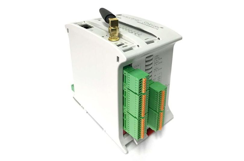
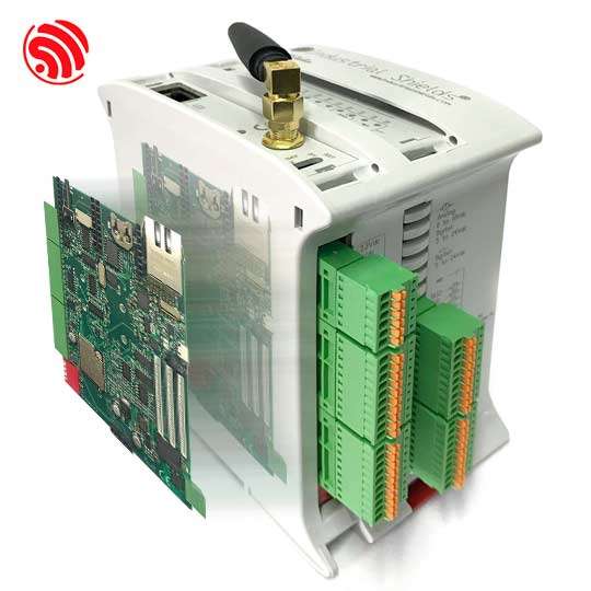
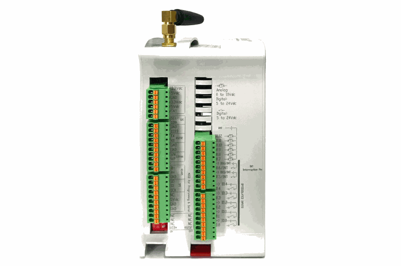
The ESP32 PLC is a powerful and versatile industrial controller that offers a wide range of functionalities. In this article, you will learn more about its pin-out characteristics, measuring things like the maximum switching frequency and the rising or falling times.
Understanding these aspects is crucial for interacting with external peripherals and developing applications that require precise timing.

Requirements
The sketches used in this blog have been tested with the ESP32 21+ PLC, but should work with another industrial PLC as long as its inputs/outputs used match their functions.
If you want to measure the open source based PLC characteristics, you will also need a precise oscilloscope capable of reading at the 100ns scale.
Digital Outputs
The ESP32 PLC uses a pin multiplexer known as the PCA9685A, which is an integrated circuit that uses I2C communication. This component allows for many more outputs than an ESP32 alone, but adds some latency which can slow down the speed at which outputs can be switched.
TaskHandle_t Task1;

void setup() {
  pinMode(Q0_0, OUTPUT);
  xTaskCreate(Task1code,"Task1",10000,NULL,25,&Task1);
}
void loop() {}

void Task1code( void * parameter ) {
  for(;;) {
    digitalWrite(Q0_0, HIGH);
    delay(10);
    digitalWrite(Q0_0, LOW);
    delay(10);
  }
}
Using this code without delay you can get up to 406.5Hz of switching frequency on any digital output with a duty cycle of 82.11%. If you want a duty cycle of 50% or less, you will need to go up to 10ms of delay for a 50 Hz 59.4%.
The rise times of these pins is 0.5µs, while the fall time is 92.4µs.
| Output Frequency | Period | Pulse Width | Delay |
| 406.5Hz | 2.46ms | 2.02ms | 0ms |
| 100Hz | 10ms | 5.98ms | 5ms |
| 50Hz | 20ms | 11.88ms | 10ms |
Digital Inputs
For digital inputs, the ESP32 PLC uses a pin multiplexer known as MCP23008, which is an integrated circuit that uses I2C communication. Although this component has 8 general I/O ports, it is used to provide the PLC of digital inputs.
TaskHandle_t Task1;
unsigned long t1, t2, t_max, t_average;

#define PIN I0_5
#define READ_TYPE digitalRead
#define N_AVERAGE 10000

void setup() {
  Serial.begin(115200);
  pinMode(PIN, INPUT);
  xTaskCreate(Task1code, "Task1", 10000, NULL, 25, &Task1);
}
void loop() {}

void Task1code( void * parameter ) {
  t_max = 0;
  t_average = 0;
  for (long i = 0; i < N_AVERAGE; i++) {
    t1 = micros();
    READ_TYPE(PIN);
    t2 = micros();
    t_average += (t2 - t1);
    if (t_max < t2 - t1) t_max = t2 - t1;
  }
  Serial.print("Max time: ");
  Serial.println(t_max);
  Serial.print("Average time: ");
  Serial.println(t_average / (float)N_AVERAGE);

  vTaskDelete(NULL);
}
The response time of the opto-isolated digital inputs averages 458µs, with a maximum of up to 888µs.
The interrupt pins, thanks to not being opto-isolated and being a directly connected to the ESP32, are much faster. The average reading time of an interrupt in is only 1µs, with a maximum measured time of 48µs.
As for non-opto-isolated digital inputs, the delay between readings averages 1500µs on average, with a maximum of 2365µs.
Analog Outputs
True analog outputs are available thanks to converting the PWM of the PCA9685A (digital outputs) with a PWM-to-DC converter and some extra circuitry for voltage matching.
TaskHandle_t Task1;

void setup() {
  pinMode(A0_5, OUTPUT);
  xTaskCreate(Task1code,"Task1",10000,NULL,25,&Task1);
}
void loop() {}

void Task1code( void * parameter ) {
  for(;;) {
    analogWrite(A0_5, 4095);
    delay(150);
    analogWrite(A0_5, 0);
    delay(150);
  }
}
As the maximum PWM frequency of the PCA9685A is around 1.5 kHz, the switching frequency of these outputs is low, around 2.26Hz. The rising times of these pins is 157.6 ms, whereas the falling time is 221.6 ms.
Analog Inputs
In the ESP32 PLC, analog inputs are made with ADS1015IDGST, a 12-bit ADC chip that communicates through I2C. It has a sampling rate of 3.3kHz.
TaskHandle_t Task1;
unsigned long t1, t2, t_max, t_average;

#define PIN I0_7
#define READ_TYPE analogRead
#define N_AVERAGE 10000

void setup() {
  Serial.begin(115200);
  pinMode(PIN, INPUT);
  xTaskCreate(Task1code, "Task1", 10000, NULL, 25, &Task1);
}
void loop() {}

void Task1code( void * parameter ) {
  t_max = 0;
  t_average = 0;
  for (long i = 0; i < N_AVERAGE; i++) {
    t1 = micros();
    READ_TYPE(PIN);
    t2 = micros();
    t_average += (t2 - t1);
    if (t_max < t2 - t1) t_max = t2 - t1;
  }
  Serial.print("Max time: ");
  Serial.println(t_max);
  Serial.print("Average time: ");
  Serial.println(t_average / (float)N_AVERAGE);

  vTaskDelete(NULL);
}
Due to the overhead with I2C communication, the maximum sampling rate drops to around 400-666Hz (a runtime of 1500µs and a maximum of 2393µs).
Direct pins
TX1
This digital pin can be used as un output only, as long as Serial1 or RS-232 are not being used. This pins have a switching frequency of 1.026MHz, with rising and falling times of 100ns each.
RX1
This digital pin can be used only as input, as long as Serial1 or RS-232 are not being used. This pin has a maximum read time of 48µs with 0.8µs average.
SPI pins (SO, SI, SCK)
These digital pins can be used as input or output, as long as SPI or Ethernet are not being used. They have rising times of 100 ns and falling times of 100ns. These pins have a maximum read time of 48µs with 0.8µs average.
GPIO 0
This pin works at 5V and can be used as digital input or output. It has a rise and fall time of 5µs each. This pin has a maximum read time of 888µs with 485.3µs average.
SCL/SDA
These digital pins have an external pull-up resistor of 2.2kOhm and operate at 5V. The rise times of these pins is 2µs, whereas their fall time is 200ns.
Although both can act as input or output, this is not recommended as all I2C peripherals that control inputs and outputs would no longer function correctly.
Summary
Inputs
| Input type | Sampling frequency - Average | Sampling frequency - Highest read time |
| Digital Interrupt (IX.5-6) | 1.25MHz (0.8µs) | 20.833kHz (48µs) |
| Digital Opto-isolated (IX.0-4) | 2183.4Hz (458µs) | 1126.1Hz (888µs) |
| Digital Non Opto-isolated (IX.7-12) | 666.67Hz (1500µs) | 422.3Hz (2365µs) |
| Analog (IX.7-12) | 666.67Hz (1500µs) | 418.06Hz (2393µs) |
| RX1 | 1.25MHz (0.8µs) | 20.833kHz (48µs) |
| SPI | 1.25MHz (0.8µs) | 20.833kHz (48µs) |
| GPIO 0 | 2060.6Hz (485.3µs) | 1126.1Hz (888µs) |
Outputs
| Output type | Maximum stable frequency | Signal Frequency - Maximum | Rise time | Fall time |
| Digital (QX.0-7) | 50Hz (59.4%) | 406.5Hz (82.11%) | 0.5µs | 92.4µs |
| Analog (AX.5-7) | 2.26Hz (50%) | 2.64Hz (37.31%) | 157.6ms | 221.6ms |
| TX1 | 1.026MHz (50%) | 1.026MHz (50%) | 100ns | 100ns |
| SPI | 1.026MHz (50%) | 1.026MHz (50%) | 100ns | 100ns |
| GPIO 0 | 200kHz (50%) | 200kHz (50%) | 5µs | 5µs |
Conclusion
To sum up, the ESP32 PLC has many features and precise timing options, which make it a strong and flexible option for different uses. It is important to know the pin-out features, such as the maximum switching speed, rise and fall times, and read times, to work well with external devices.
The PLC's digital outputs, digital inputs, analog outputs, and analog inputs each have specific performance features that should be considered when creating and developing applications.
With the right setup and careful attention to these details, the ESP32 PLC can provide consistent and accurate results for your industrial automation and control requirements.


Analysis of the ESP32 PLC pinout time response