Introduction
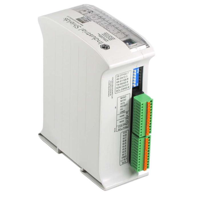
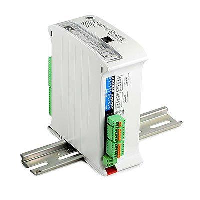
The Ardbox analog PLC is a versatile industrial controller that offers a wide range of functionalities. In this article, you will learn more about its pin-out characteristics, such as maximum switching frequency and rise or fall times. Understanding these aspects is crucial for interfacing with external peripherals and developing applications that require precise timing.
Requirements
If you want to measure the PLC characteristics, you will also need a precise oscilloscope capable of reading at the 100ns scale.
Digital output
The Arduino Ardbox Analog PLC has 10 digital outputs (7 of which are also PWM), which can work within the 5-24V range. Remember the output voltage depends on the QVdc pin, you can learn more about them on this post about digital outputs.
void setup() {
  for(;;){
    digitalWrite(Q0_0, HIGH);
    delay(500);
    digitalWrite(Q0_0, LOW);
    delay(500);
  }
}

void loop() {}
This program generates a 50% duty cycle square signal with a 1Hz frequency. Using an oscilloscope, the rise and fall times of the resulting signal at the output can be observed:
- Rise time: 0.5µs
- Fall time: 100.8µs
Adjusting the delay on the code we can change the output frequency. Here are some examples:
Output frequency | Period | Pulse width | Delay |
2.457kHz | 413µs | 246.5µs | 200µs |
1kHz | 1ms | 0.54m | 500µs |
A signal of up to 2.5kHz can be achieved, although the duty cycle is a bit higher than 50%. On even higher frequencies, the duty cycle is even higher, whereas on lower frequencies it goes down to a 50%, the expected value.
Digital input
There are 10 digital inputs in the Arduino Ardbox Analog PLC, all with a working range from 0 to 3.3Vdc up to 24Vdc :
- 1 digital input (I0.1)
- 1 interrupt pin (I0.0)
- 8 inputs than can be used as both analog or digital (I0.2 - I0.9).
With this program, their average and maximum sampling speed can be measured.
#define N_TIMES 10000

unsigned long t1, t2, t_max, t_average;

void setup() {
  Serial.begin(115200);
  while (!Serial);

  t_max = 0;
  t_average = 0;

  for (long i = 0; i<N_TIMES; i++) {
    t1 = micros();
    digitalRead(I0_5);
    t2 = micros();
    t_average += (t2-t1);
    if (t_max < t2-t1) t_max = t2-t1;
  }

  Serial.print("Max time: ");
  Serial.println(t_max);
  Serial.print("Average time: ");
  Serial.println(t_average/(float)N_TIMES);
}

void loop() {}
The three types of pins that can be used as digital input all have the same time responses:
- Average sampling time: 5.46µs
- Maximum sampling time: 16µs
Analog output
The Arduino Ardbox Analog PLC features 7 analog outputs with a 8-bit resolution and a 0-10V operating range.
In order to measure the response time of the analog outputs we can use an oscilloscope and the following code to measure the rise and fall times of the signal:
void setup() {
  for(;;){
    analogWrite(A0_5, 4095);
    delay(1000);
    analogWrite(A0_5, 0);
    delay(1000);
  }
}

void loop() {}
Measuring with an oscilloscope we get the following times:
- Rise time: 226ms
- Fall time: 214ms
Considering 226ms as the worse time, we can achieve an output signal with a frequency of 2.21Hz.
Analog input
The analog inputs in the Arduino Ardbox allow to measure voltages between 0V and 10V, returning a value with a resolution of 10 bits (0-1023). There are 8 analog inputs.
The average and maximum sampling time of the analog inputs can be measured with this program:
#define N_TIMES 10000

unsigned long t1, t2, t_max, t_average;

void setup() {
  Serial.begin(115200);
  while (!Serial);

  t_max = 0;
  t_average = 0;

  for (long i = 0; i<N_TIMES; i++) {
    t1 = micros();
    analogRead(I0_5);
    t2 = micros();
    t_average += (t2-t1);
    if (t_max < t2-t1) t_max = t2-t1;
  }

  Serial.print("Max time: ");
  Serial.println(t_max);
  Serial.print("Average time: ");
  Serial.println(t_average/(float)N_TIMES);
}

void loop() {}
The results obtained from the program executed are:
- Average sampling time: 112.56µs
- Maximum sampling time: 1144µs
Direct Pins
Lastly, there are some direct Arduino Pins available too. These pins are intended to use with SPI and I2C communications, but if these protocol are not used, they can be programmed as regular Arduino pins to be used as digital input or output.
Keep in mind that these pins need to configured with the pinMode() function according to how they are going to be used. as input or output.
SPI
The SPI pins are the SCK, MOSI, and MISO which correspond to the pins 15, 16 and 14 of the Arduino Leonardo, respectively.
- Digital input: these pins have an average sampling time of 5.46µs, with a maximum time of 16 µs.
- Digital output: the output has a rise and fall time of 43.2ns both.
I2C
The I2C pins are the SCL and SDA, corresponding to the Arduino pins 3 and 2, respectively.
- Digital input: the average sampling time of the inputs is 5.48µs, and the maximum is 16µs.
- Digital output: the generated signal has a rise and fall time of 100ns both.
Summary
Inputs
| Input type | Sampling frequency - Average | Sampling frequency - Highest read time |
| Digital (IX.2-9 and IX.0-1) | 183.15kHz (5.46µs) | 62.5kHz (16µs) |
| Analog (IX.2-9) | 8.88kHz (112.56µs) | 874.13Hz (1144µs) |
| SPI/I2C | 183.15kHz (5.46µs) | 62.5kHz (16µs) |
Outputs
| Output type | Maximum stable frequency | Signal Frequency - Maximum | Rise time | Fall time |
| Digital (QX.0-9) | 1kHz (54%) | 2.457kHz (59.69%) | 0.5µs | 100.8µs |
| Analog (AX.0-6) | 2.21Hz (50%) | 2.21Hz (50%) | 226ms | 214ms |
| SPI/I2C | 145kHz (50%) | 40kHz (50%) | 43.2ns | 43.2ns |
Conclusion

In conclusion, the Ardbox PLC is packed with numerous features and precise timing options, making it a versatile and robust solution for a wide range of applications. To ensure perfect compatibility with external devices, it is essential to have a good understanding of the pin characteristics such as maximum switching speed, rise and fall times and read times.
When designing and developing applications, it is essential to consider the specific performance characteristics of the PLC's digital outputs, digital inputs, analogue outputs and analogue inputs.
By configuring the system properly and paying meticulous attention to these particularities, the Ardbox PLC can consistently deliver accurate and reliable results to meet your industrial automation and control needs.


Analysis of the Arduino Ardbox Analog PLC pinout time response