
Introduction
In this post, we are going to see how to connect our industrial controller Arduino -PLC- to the Distribution Panel in a regulated way, following the protocol rules. We will review the connection between the PLC controller and the Distribution Panel and between two PLCs for industrial automation, the safety distances in the installation, the ventilation cautions that have to be followed in certain circumstances, the wiring and the material needed and a few more things. After all the theoretical explanations, we will see a practical video with an example of everything explained previously.
Requirements
Here you have the link to check out the available devices in our website which you can use to do this installation:

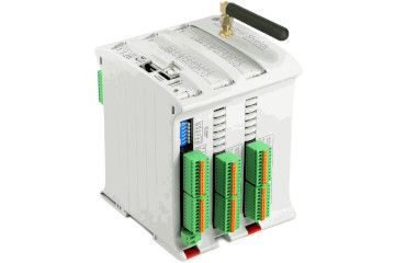
WiFi & Bluetooth PLC Family
Integrated module with 2.4 GHz Wi-Fi and Bluetooth with the TSMC ultra-low-power 40 nm technology.
It can be used as an access point to create the wireless network infrastructure, such as a bridge to connect computers in the network.

20 I/Os Controller Family
Up to 20 inputs and outputs.
Digital, Analog and Relay IOs to ensure you can work with multiple options available.
Industrial Protocols available:
RS485 · RS232 · SPI · I2C · Modbus RTU
Ethernet Controller Family
Up to 58 IOs are available.
Multiple protocols and other options at your disposal like LoRa, WiFi, GPRS, or DALI.
GPRS / GSM Controller Family
PLC is ideal for remote monitoring, data logging and remote access, diagnostics and control, using short text messages (SMS).
Adjust the messages to send from a device with static (text) or dynamic (text and values) content.
Here you can find more material like the Power Supplies or the Din Rails:
Theoretical Explanation
You can find an extended version of the information shown here in the Installation and Maintenance and the Mechanical Characteristics (DIN Rail Mounting) chapters of the User Guides.
Connections
First of all, install the DIN Rail in a proper way following the recommended safety distances. Place the programmable logic controller (PLC) in its location of the DIN Rail and start the wiring. Make the connections between the Power Supply and the industrial Arduino PLC (ALWAYS WITHOUT CONNECTING IT TO THE ELECTRIC POWER UNTIL THE END FOR SAFETY REASONS) and make the connections between the different PLCs or the industrial controller and the inputs and outputs like sensors or actuators.
Installation notes
- The installation position should be free from the following: dust or oil smoke, conductive dust, corrosive or flammable gas, high temperature, condensation, and rain.
- Besides, vibration and impact also affect the PLC normal operation and shorten its lifespan; electric shock, fire or misact also damages the product. During drilling or wiring, prevent the metal particles or wire segments from falling into the PLC casing, which may cause fire, fault or misact.
- After the PLC installation, clean the ventilation duct to prevent blocking, which may cause bad ventilation, or even fire, faults or misact.
- Do not online connect, plug or unplug cables, which is apt to cause electric shock or damage the circuit. Installation and wire connection must be firm and reliable. The poor connection could cause misact.
- Use shielded twisted pair for the I/O of high-frequency signal and analog signal to improve system IMS.
- The only way to disconnect the equipment from the electrical network is by removing the connectors that feed the equipment. Once installed in the electrical cabinet it is very important to ensure the power connectors for proper operation.
Distances
Always separate the devices that generate high voltage and high electrical noise from the PLC. When configuring the layout of the PLC inside your panel, consider the heat-generating devices and locate the electronic-type devices in the cooler areas of your cabinet. Reducing exposure to a high-temperature environment will extend the operating life of any electronic device. Consider also the routing of the wiring for the devices in the electric cabinet. Avoid placing low-voltage signal wires and communications cables in the same tray with AC power wiring and high energy, rapidly-switched DC wiring. Provide adequate clearance for cooling and wiring PLC. Is designed for natural convection cooling. For proper cooling, you must provide a clearance of at least 25 cm above and below the devices. Also, allow at least 25 cm of depth between the front of the modules and the inside of the enclosure.
Ventilation
The maximum temperature supported by our devices is 60 Celsius degrees so, according to that, you have to ensure a correct environment for the device and, if the temperatures are going to be higher than this number, provide a refrigeration system with fans and a ventilation system.
Safety rules
- Do not disassemble or modify the modules. This could lead to breakdowns or malfunctions and could lead to injuries or fire.
- All types of radio communication devices, including mobile phones and personal handy-phone systems (PHS), must be kept more than 25 cm away from the PLC in all directions. Failure to observe this precaution exposes malfunctions caused by an excess of temperature.
- Disconnect the external power supply of the system (on all phases) before connecting or disconnecting a module. Failure to observe this precaution may cause faults or malfunctions of the module.
- Tighten the screws of the terminal ports and the screws of the connectors within the prescribed tightening torque. Insufficient tightening can lead to loose parts or wires and cause malfunctions. Excessive tightening can damage the screws and/or the module, with the risk of falling, short circuits and malfunctions.
- Before handling a module, dispose of the electrostatic charge accumulated by the human body by touching a suitable conductive object. Failure to observe this precaution may cause faults or malfunctions of the module.
Video
How to connect the PLC Arduino to the Distribution Panel