Index
1. Introduction
2. UPS Shield
3. Technical Specifications
4. The Real-Time Clock
5. The RS-485 interface
6. Discharge supercapacitors
7. Connecting two Industrial Arduino PLCs using RS-485 to open and close a relay
Introduction
In this post, you will find general information about the UPS Shield and the configuration that has to be done to the Raspberry Pi.
UPS Shield
The UPS Shield module is a supercapacitor based energy storage. It contains two independent DC/DC converters. The first one is a bidirectional step-up/step-down converter working as the interface between the stable 5V supply rail and the supercapacitor. During charging the converter works in step-down mode and transports energy from the external power supply to the supercapacitor. In case of a power failure, the load device (Raspberry Pi or another SBC) is supplied from the supercapacitor via DC/DC converter in step-up mode. The second DC/DC converter is a Front-end step-down converter. The only function is converting a high input down to 5.1V for the 5V rail.
Technical Specifications
General
| Parameter | Value | Conditions |
| Max. Total Backup time Ttb | Min. 57 s Typ. 81 s | Operation until supercapacitors not discharged. Tamb = 25 ºC. |
| Backup time for Sort-term power failure Tst | Min. 22 s Typ. 31 s | Operation until supercapacitors not discharged. Tamb = 25 ºC. |
| Charge time (fast charge) = default configuration | Typ. 25 s | Operation until supercapacitors not discharged. Tamb = 25 ºC. |
| Operating time (slow charge) | Typ. 60 s | Operation until supercapacitors not discharged. Tamb = 25 ºC. |
| Operating temperature range (module) | -40 ºC to +85 ºC -25 ºC to +70ºC | Assembled PCB Including Push-Button and Screw terminals |
| Operating temperature range (supercapacitors) | -40 ºC to + 60ºC | Supercapacitor type: 22F / 2.7V / DxL = 16 x 26 mm |
Input
| Parameter | Value | Conditions |
| Input Voltage Range | 7V DC ... 28 DC | at screw terminal |
| Average Input Current | 1 A 0.5 A | Charge mode+RPi3 Booting at Vin = 12 V Charge mode+RPi3 Booting at Vin = 24 V |
| Current consumption | Typ. 15 mA | Normal operation (No charge mode, no Shutdown mode), Tamb = 25 ºC |
| Parameter | Value | Conditions |
| Output voltage range | 4.75 V DC ... 5.25 V DC | |
| Output current range | 0 Aavg ... 1 Aavg | |
| Typ. output ripple | 10 mVpp | At shutdown mode, Tamb = 25 ºC, ripple at fSW = 1200 kHz |
Supercapacitor Interface
| Parameter | Value | Conditions |
| Working voltage at supercapacitor contacts | 1 V ... 5.25 V | |
| Peak current through supercapacitor | 7 A | |
| Charging method | 7.5 W (fast charge, default) = 1.5 A at 5 V 2.5 W (slow charge) = 0.5 A at 5 V | Constant power charging Constant power charging |
| Balancing | +/- 300 mA | Active balance circuit for two supercapacitors in series |
The Real-Time Clock
The board contains a DS3231 integrated circuit communicating via I2C-bus with the RaspberryPi. A Lithium Coin Battery supplies the RTC chip when the Raspberry Pi is not powered on. We recommend using the CR2032 battery.
| Parameter | Value | Conditions |
| RTC chip type | DS3231 | Supported by the Raspbian OS |
| Battery holder | CR2032 | 3 V, Lithium |
| Battery Lifetime | > 20 years | at capacity 200 mAh |
| Communication | I2C-bus | Pins 3 and 5 of the GPIO interface (SDA and SCL), requires RTC driver installed on the RPi |
In the file /boot/config.txt uncomment the line
dtparam=i2c_arm=on
and at the end add the line
dtoverlay=i2c-rtc,ds3231
The RS-485 interface
In the file /boot/config.txt add the line
enable_uart=1
| Parameter | Value | Conditions |
| RS-485 Interface Communication Type | 2-wire, half duplex | Transceiver chip ISL8483E |
| RX/TX direction control | Controlled by GPIO24 | Diver enabled by a low TX data bit Driver disabled 25 us after the end of a low TX data bit |
| Failsafe biasing | 390R to GND 390R to 5V | |
| Line Termination | 120R | 390R//220R//390R+2*10R |
| Protection | ESD to +/- 15 kV | No Surge/Burst protection |
| Echo-feature | RX always enabled TX enabled at data | Optional |
| Data transmission speed | 0...250kbps slew rate limited | 25 us transmission pause between TX and RX required |
The driver-enable line follows the data with a short delay (25 μs) before disabling the driver. There is no need to adjust the time constant for different transmission speeds. The automation direction control works from zero to maximum transmission baud rate. The only requirement is a 25 μs transmission pause between sent and receives data. Thi short time interval corresponds to a time interval of about 3 data bits at 115 kbps. At 9600 bps the 25 μs time interval corresponds to a fraction of one data bit.
Instead of keeping the transmitter enabled for the entire transmission, the driver is enabled on the leading edge of the start bit or any logic low at the drivers in out. It also disables the driver 25 μs after the leading edge of the stop bit or any logic high at the driver's input. When the driver is disabled, the biasing resistors ensure the receiver's output is a logic high.
Discharge supercapacitors
| Parameter | Value | Condition |
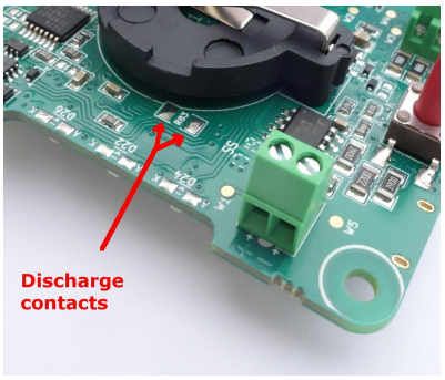
| Discharge load | 2 Ohm Meander PCB trace used as shunt monitor | at 25 ºC |
| Typical Discharge Time ar default 2x22F supercapacitors | 1 min. | Short the pads R83 with a tweezer |

UPS Shield for Raspberry Pi