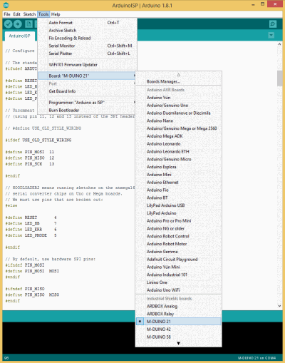
This post, it is showed how to use the mapping pins of Industrial Shields boards. Before using these pins, it is necessary to download the Industrial Shields boards. Follow the next link to download the boards.

These boards provide you Industrial Shields PLC mapping. How does it work?
For example, with these boards, it is not necessary to figure out what Arduino pin belong to the Industrial Shields PLC. Just using directly this PLC pin, Arduino IDE will arrange the mapping for you. To reference to the Industrial Shields Pins, it must be typed like this:
- Digital Outputs: QX_X
- Analog Outputs: AX_X
- Relay Output: RX_X
- Inputs (regardless if it’s analog or digital): IX_X
Next, is shown a sketch example:
// In this case is selected the M-DUINO 58 board
void setup() {
             }

////////////////////////////////////////////////////////////////////////////////////////
void loop() {
  // Toggle pins once a second
  digitalWrite(Q0_0, HIGH);
  digitalWrite(Q0_1, HIGH);
  //...
  analogWrite(A0_0, 255);
  analogWrite(A0_1, 528);
  //...
  digitalWrite(R0_0, HIGH);
  digitalWrite(R0_1, HIGH);
  //...
  delay(1000);

  digitalWrite(Q0_0, LOW);
  digitalWrite(Q0_1, LOW);
  //...
  analoglWrite(A0_0, 100);
  digitalWrite(A0_1, 0);
  //...
  digitalWrite(R0_0, LOW);
  digitalWrite(R0_1, LOW);
  //...

  delay(1000);
}
How to use the mapping pins of Industrial Shields Boards