Introduction
The devices of the ESP32 PLC family have a defined number of digital outputs. All of them can be programmed as PWM outputs, if required. As we know, the PWM (Pulse Width Modulation) is a kind of voltage signal used to send information or to modify the amount of power sent for each charge. In this blog you are going to see how to configure PWM outputs.
Requirements
What is a PWM and how it works?
PWM stands for Pulse Width Modulation, which is a technique used to control the amount of power delivered to a device. It is commonly used in electronic systems to control the speed of motors, the brightness of LEDs, and the voltage supplied to various components.
The basic principle behind PWM is to rapidly switch the power on and off at a specific frequency, while varying the duration of the "on" and "off" periods. By adjusting the duty cycle (the percentage of time that the power is "on" relative to the total cycle time), the average power delivered to the device can be controlled.
PWM Outputs in ESP32 based PLCs
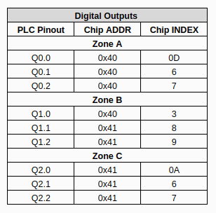
The ESP32 based PLC outputs are not direct ESP32 pins. Instead, I2C expansion chips are used. Depending on the PLC version, there are up to 2 expansion chips, with I2C addresses 0x40 and 0x41.
Each output pin is associated with a pin on the expansion chip. The duty cycle on each pin is independent from the others and configurable. Each output has its own 12-bit resolution (4096 steps), which is used to set the duty cycle, for example:
0% duty cycle: 0
50% duty cycle: 2048
100% duty cycle: 4095
The frequency, on the contrary, is configurable only by chip, which means that all the outputs on one chip will output the same frequency. This means that the user must be careful when changing the frequency of a chip, since all its outputs will be affected. The frequency can take a value between 24Hz and 1526Hz.
The following tables show which internal pin and address corresponds to each of the PLCs outputs:
Analog-Digital Outputs:

Analog-Digital-Relay Outputs:

Code example
In order to use the Output of the PLCs the "inudstrialshields-esp32" boards package needs to be installed. If you don't have it already, it can be installed following this tutorial.
There is no need to include any library to use the outputs. However, the pins need to be set as outputs, which can be done like this:
pinMode(Q0_0, OUTPUT);
The duty cycle can be configured using the "analogWrite()" function, which takes as argument the pin we want to configure and the duty cycle, which is an int that should be between 0 and 4095:
analogWrite(Q0_0 , 3000);
Finally, to configure the output frequency of each chip, use the "analogWriteSetFrequency()" function. It takes as arguments the address of an I2C chip (for example 0x40) and an int with the frequency we want to use (the chip can output frequencies between 24Hz and 1526Hz, higher or lower frequencies will be set to the correspoding limit).
analogWriteSetFrequency(0x40, 1000);
Note: after changing the frequency of a chip, the state of its outputs is reset, meaning that their duty cycle needs to be set again.
ESP32 PLC: PWM Output