Basic wired communication: RS485, RS232, I2C, SPI and serial TTL
An M-Duino or Ardbox rarely works alone. It talks to sensors, drives, HMIs and other PLCs over one of a handful of wired protocols. Picking the right one starts with a simple question: does this link connect exactly two devices, or does it need to share one line among several?
What you will learn
- Tell point-to-point links from shared buses.
- Choose the right protocol for a given project.
- Avoid the four wiring mistakes behind most RS485 failures.
- Run a first test on RS485 and I2C.
Two topologies, five protocols
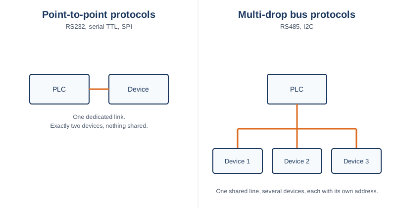
RS232 and serial TTL connect exactly two devices over dedicated wires, the classic case being a PLC talking to a single PC or a single sensor. SPI is also point-to-point in practice, one PLC to one chip, even though the electrical signaling is different from RS232 or TTL. RS485 and I2C instead share one line among several devices, each identified by an address, which is what makes them the natural choice when one PLC needs to talk to many devices without running a dedicated cable to each one.
RS485: the industrial field bus
RS485 is the default choice for wiring multiple field devices to a PLC over long cable runs across a plant, which is why it shows up as a dedicated port and why Modbus RTU runs over it. Multiple devices share the same pair of wires, each with its own address.
The four mistakes behind most RS485 failures
- Swapped A and B wires. Manufacturers label the pair inconsistently. If nothing communicates, swapping the two wires on one device is the first test.
- Missing or doubled termination. A bus needs a termination resistor at each of its two physical ends, not in the middle and not on every device.
- No common reference. Devices powered from different supplies may need their grounds referenced, as indicated in their datasheets.
- Mismatched settings. Baud rate, parity and stop bits must be identical on every device on the bus.
Half duplex or full duplex?
Half duplex is the common case on an RS485 bus: devices share one pair and take turns talking. The Ardbox supports half duplex only. The M-Duino family is the one that offers both modes, selected with a physical switch on the PLC (a feature exclusive to the M-Duino family). On an M-Duino, check the position of that switch in your model's documentation, because the mode you pass in the sketch must match it.
A first RS485 test
This sketch shows on the Serial Monitor every byte that arrives on the RS485 port. We use half duplex because it works on both the Ardbox and the M-Duino. Industrial Shields boards provide the RS485 object, use it instead of a numbered hardware serial port.
#include <RS485.h>

void setup() {
  Serial.begin(9600);
  RS485.begin(9600, HALFDUPLEX);
}

void loop() {
  if (RS485.available()) {
    Serial.write(RS485.read());
  }
}
On an M-Duino, set the switch to half duplex before testing. If you later move to full duplex, change the sketch to FULLDUPLEX and the switch with it.
RS232 and serial TTL: simple point-to-point links
RS232 is still common for connecting to legacy equipment that only speaks that standard. Serial TTL is the same idea at logic-level voltages, often used for short, on-board or panel-internal links rather than long cable runs. Never connect an RS232 line directly to a TTL pin, their voltage levels are different and you need a level converter.
I2C and SPI: short-range buses for nearby peripherals
I2C and SPI are built for short distances, typically a few centimeters to a couple of meters, connecting the PLC to nearby expansion modules or sensor breakout boards rather than devices spread across a plant. I2C shares one bus among many addressed devices, while SPI dedicates a chip-select line per device even though data lines are shared.
A first I2C test: find what is on the bus
This standard Arduino sketch scans the I2C bus and prints the address of every device that answers. It is the quickest way to confirm that a device is wired correctly.
#include <Wire.h>

void setup() {
  Serial.begin(9600);
  Wire.begin();
  for (byte address = 1; address < 127; address++) {
    Wire.beginTransmission(address);
    if (Wire.endTransmission() == 0) {
      Serial.print("Device found at 0x");
      Serial.println(address, HEX);
    }
  }
}

void loop() {
}
Choosing a protocol for your project
As a starting point: reaching across a plant floor to multiple devices points to RS485. Talking to one nearby chip or expansion board points to I2C or SPI. Connecting to older single-device equipment points to RS232 or serial TTL. The exact wiring and connector of each protocol on your board variant is in the pinout diagrams from the previous lesson.
Next lesson: Ethernet, giving the PLC a stable address and a first TCP connection. Take the quiz below first to check what you have learned.
No hay comentarios por ahora.
para ser el primero en comentar.