Antes de empezar
Modbus RTU es un protocolo ampliamente utilizado para interactuar con dispositivos esclavos, escribir y leer en sus registros, y controlar múltiples puntos finales al mismo tiempo. Para una introducción básica a Modbus RTU, consulta las siguientes entradas de blog:
Configuración básica
In this example, we used a Touchberry Panel, but the configuration and performance of the UPSafePi is the same, as it used the same GPIOs.
El Touchberry Panel actuará como el maestro, ya que la pantalla que incorpora puede ser muy útil para mostrar los estados actuales de todos los dispositivos conectados a través de Modbus RTU, como otros PLCs de Industrial Shields, controladores genéricos o sensores.
Para conectar los dispositivos, conecta todos los pines A+ y todos los pines B- utilizando pares de cables trenzados para minimizar las reflexiones de señal. Luego, enciende el Touchberry Panel y conecta un teclado y un ratón utilizando los puertos USB que están debajo.
First of all, open a terminal and install the libgpiod-dev depencendy:
sudo apt install libgpiod-dev
Then, create a folder to store all the files:
mkdir modbusrtu && cd modbusrtu
Then download the corresponding files and store them under the modbusrtu directory.
This two files compose the Modbus RTU library for Touchberry Panel. The Raspberry Pi port which is used to work over RS-485 is the /dev/ttyAMA0.
OS related configuration
Before starting, ensure you Operative System version is updated to the newest version (Bookworm 12 at the moment of writing this post). You can check your own version with cat /etc/os-release.
Before starting, add the following line in /boot/firmware/config.txt. You can open this file with:
sudo nano /boot/firmware/config.txt
By default, the Raspberry Pi serial port is /dev/ttyS0, but it is a miniUART and, because of its hardware limitations, lacks parity control, leading to incompatibility with most of Modbus RTU slave devices. The UART that has parity control is automatically occupied by the Bluetooth device.
In order to change that, we use the previous configuration. We specify the Raspberry Pi's Bluetooth device to use this miniUART, so the RPI's serial port can automatically occupy the UART, which has parity control. This serial port in specific is /dev/ttyAMA0.
Finally, reboot the device.
Código de prueba 1
Para probar la funcionalidad de la biblioteca, podemos usar un script que toma como parámetros las siguientes variables
- Identificador de esclavo.
- Velocidad de baudios.
- Serial configuration
- Código de función.
- Dirección.
- Valor que escribir / Cantidad a leer.
El código es el siguiente:
#include <stdio.h>
#include <unistd.h>
#include <stdlib.h>

#include "modbus.h"

///////////////////////////////////////////////////////////////////////////////////////
int main(int argc, char* argv[]) {

  if (argc <= 5) {
    printf("Missing parameters\n");
    return 1;
  }

  int slave_id   = atoi(argv[1]);
  int baudrate   = atoi(argv[2]);
  char *serial_c = argv[3];
  int fc         = atoi(argv[4]);
  int address    = atoi(argv[5]);

  uint16_t i_reg[100];
  char d_inp[100];
  char coils[100];
  uint16_t h_reg[100];

  modbus_err_t err;

  // Start modbus
  if (modbus_begin(slave_id, baudrate, getSerialConfig(serial_c))) {
    return 1;
  }

  // Read digital outputs
  if (fc == 0x01) {
    int quantity = atoi(argv[6]);

    err = read_coils(address, quantity, coils);
    if (err != NO_ERR) {
      fprintf(stderr, "Error: %s\n", getErrorCode(err));
      return 1;
    }
    for (int i = 0; i < quantity; i++) {
      printf("%d", coils[i]);
      if (i < quantity - 1) printf(",");
    }
    printf("\n");
    return 0;
  }

  // Read digital inputs
  if (fc == 0x02) {
    int quantity = atoi(argv[6]);

    err = read_discrete_inputs(address, quantity, d_inp);
    if (err != NO_ERR) {
      printf("Error: %s\n", getErrorCode(err));
      return 1;
    }
    for (int i = 0; i < quantity; i++) {
      printf("%d", d_inp[i]);
      if (i < quantity - 1) printf(",");
    }
    printf("\n");
    return 0;
  }

  // Read analog outputs
  if (fc == 0x03) {
    int quantity = atoi(argv[6]);

    err = read_holding_registers(address, quantity, h_reg);
    if (err != NO_ERR) {
      printf("Error: %s\n", getErrorCode(err));
      return 1;
    }
    for (int i = 0; i < quantity; i++) {
      printf("%hu", h_reg[i]);
      if (i < quantity - 1) printf(",");
    }
    printf("\n");
    return 0;
  }

  // Read input registers
  if (fc == 0x04) {
    int quantity = atoi(argv[6]);

    err = read_input_registers(address, quantity, i_reg);
    if (err != NO_ERR) {
      printf("Error: %s\n", getErrorCode(err));
      return 1;
    }
    for (int i = 0; i < quantity; i++) {
      printf("%hu", i_reg[i]);
      if (i < quantity - 1) printf(",");
    }
    printf("\n");
    return 0;
  }

  // Write digital output
  if (fc == 0x05) {
    int value   = atoi(argv[6]);

    err = write_single_coil(address, value);
    if (err != NO_ERR) {
      printf("Error: %s\n", getErrorCode(err));
      return 1;
    }
    return 0;
  }

  // Write analog output
  if (fc == 0x06) {
    int value   = atoi(argv[6]);

    err = write_single_register(address, value);
    if (err != NO_ERR) {
      printf("Error: %s\n", getErrorCode(err));
      return 1;
    }
    return 0;
  }

  // Write digital outputs
  if (fc == 0x0F) {
    int quantity  = atoi(argv[6]);
    if (argc - 7 != quantity) {
      printf("Error: Not enough values for coils, expected %d, got %d\n", \
             quantity, argc - 7);
      return 1;
    }
    for (int i = 0; i < quantity; i++) {
      coils[i] = atoi(argv[i + 7]);
    }

    err = write_multiple_coils(address, coils, quantity);
    if (err != NO_ERR) {
      printf("Error: %s\n", getErrorCode(err));
      return 1;
    } else {
      return 0;
    }
  }

  // Write multiple registers
  if (fc == 0x10) {
    int quantity = atoi(argv[6]);
    if (argc - 7 != 2 * quantity) {
      printf("Error: Not enough values for registers, expected %d, got %d\n", \
             quantity * 2, argc - 7);
      return 1;
    }

    for (int i = 0; i < quantity; i++) {
      h_reg[i] = atoi(argv[i + 7]);
    }

    err = write_multiple_registers(address, h_reg, quantity);
    if (err != NO_ERR) {
      printf("Error: %s\n", getErrorCode(err));
      return 1;
    }
    return 0;
  }

  modbus_close();
}
Por lo que se puede ver, la biblioteca adapta los siguientes Códigos de Función
- FC 1: Leer bobinas.
- FC 2: Leer entradas discretas (Discrete Inputs).
- FC 3: Leer registros de retención (Holding Registers).
- FC 4: Read Input Registers.
- FC 5: Escribir una sola bobina.
- FC 6: Escribir un solo registro.
- FC 15: Write Multiple Coils.
- FC 16: Write Multiple Registers.
Para compilar el código usa:
gcc -o main main.c modbus.c -lgpiod
Y para executar
./main <slave_id> <baudrate> <serial_config> <fc> <address> <value/quantity>
Por ejemplo, echa un vistazo a la siguiente imagen:
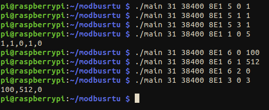
- Los primeros comandos son con FC: 5 (escribir bobinas). Esto configura las bobinas 0, 1 y 3 a 1.
- Al leer las bobinas (FC: 1), se puede ver que se han escrito correctamente.
- A continuación, FC: 6, que es escribir registros. Escribimos 100 en el registro 0, 512 en el registro 1 y 0 en el registro 2.
- FC: 3 es leer registros de retención, y podemos ver claramente que funciona.
Este método de establecer los parámetros en la línea de comandos puede ser muy útil al llamar al script desde una aplicación en Python o Node-RED, ya que este script es muy flexible y se puede llamar varias veces para interactuar con más de un esclavo, cambiando el ID del esclavo, la velocidad de baudios o el código de función.
Código alternativo
En lugar de establecer los parámetros en la línea de comandos, podemos crear un script para hacer algunas peticiones de forma secuencial. Por ejemplo, hagamos lo mismo que se ve en la imagen anterior:
#include <stdio.h>
#include <unistd.h>
#include <stdlib.h>

#include "modbus.h"

#define QUANTITY_COILS 5
#define QUANTITY_REGS  3

///////////////////////////////////////////////////////////////////////////////////////
int main(int argc, char* argv[]) {

  modbus_err_t err;

  // Start modbus
  if (modbus_begin(31, 38400, SERIAL_8E1)) {
    return 1;
  }

  // Write coils
  uint8_t values[QUANTITY_COILS] = {1, 1, 0, 1, 0};
  uint8_t coils[QUANTITY_COILS];

  if (write_multiple_coils(0, values, QUANTITY_COILS) != NO_ERR) {
    return 1;
  }

  // Read coils
  if (read_coils(0, QUANTITY_COILS, coils) != NO_ERR) {
      return 1;
  }
  for (int i = 0; i < QUANTITY_COILS; i++) {
    printf("%d", coils[i]);

    if (i < QUANTITY_COILS - 1) {
      printf(",");
    }
  }
  printf("\n");

  // Write registers
  uint16_t regs[QUANTITY_REGS] = {100, 512, 0};
  uint16_t h_reg[QUANTITY_REGS];

  if (write_multiple_registers(0, regs, QUANTITY_REGS) != NO_ERR) {
    return 1;
  }

  // Read holding registers
  if (read_holding_registers(0, QUANTITY_REGS, h_reg) != NO_ERR) {
    return 1;
  }
  for (int i = 0; i < QUANTITY_REGS; i++) {
    printf("%hu", h_reg[i]);

    if (i < QUANTITY_REGS - 1) {
      printf(",");
    }
  }
  printf("\n");

  modbus_close();
}
Usando este código y compilando de la misma manera que antes (gcc -o testt test.c modbus.c -lgpiod), obtenemos este resultado:
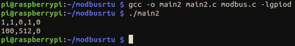
El resultado es el mismo, hemos escrito y leído con éxito de acuerdo con la prueba que hicimos previamente.
Un paso más allá
Gracias a la flexibilidad de la biblioteca, es posible crear y desarrollar una interfaz de usuario con Node-RED. Por ejemplo, echa un vistazo a este diseño simple:

Este es solo un enfoque básico. Se puede tomar como un boceto inicial, pero debe adaptarse a las necesidades del usuario. El flujo código se adjunta a continuación. Recuerda usar el primer código visto en esta publicación y compilarlo nombrando el archivo ejecutable como "cmd" (gcc -o cmd test.c modbus.c -lgpiod).
flows.json