
INTRODUCCIÓN
La función Modbus RTU Write Multiple Holding Registers (código de función Modbus 16) sirve para escribir un bloque de registros contiguos (de 1 a 123 registros) en un dispositivo remoto.
En este artículo escribiremos varios holding registers desde el PLC configurado como maestro hasta el PLC configurado como esclavo, con valores aleatorios entre 0 y 256.
MODBUS RTU
Para saber más sobre Modbus RTU y cómo funciona la librería, consulta el siguiente artículo:
REQUISITOS DE HARDWARE
- 2x M-Duino Arduino PLC >
- Fuente de alimentación >
- Cable tipo B, para programar el PLC basado en Arduino
- Dos cables de par trenzado, para RS485.
REQUISITOS DE SOFTWARE
CONEXIONES
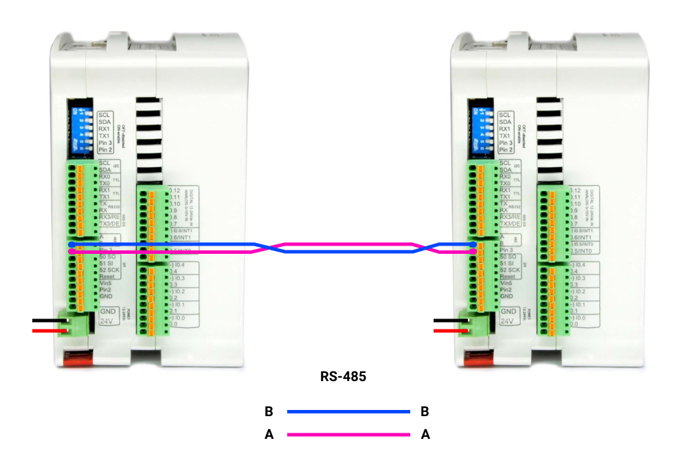
Para establecer la comunicación Modbus RTU, haremos lo siguiente:
1. Alimenta el PLC con una tensión entre 12 y 24 V.
2. Conecta los cables por RS-485. Se usa un par trenzado: un cable de A+ a A+ y el otro de B- a B-.
3. Pon el interruptor rojo en Half-Duplex: HD
MODBUS RTU MAESTRO: WRITE MULTIPLE HOLDING REGISTERS
Para configurar un M-Duino Arduino PLC como maestro y el otro como esclavo, hay que programar cada uno con su código. Para programar el maestro, abre un archivo nuevo en Arduino IDE y pega el código siguiente:
/*
   Copyright (c) 2018 Boot&Work Corp., S.L. All rights reserved

   This program is free software: you can redistribute it and/or modify
   it under the terms of the GNU Lesser General Public License as published by
   the Free Software Foundation, either version 3 of the License, or
   (at your option) any later version.

   This program is distributed in the hope that it will be useful,
   but WITHOUT ANY WARRANTY; without even the implied warranty of
   MERCHANTABILITY or FITNESS FOR A PARTICULAR PURPOSE.  See the
   GNU Lesser General Public License for more details.

   You should have received a copy of the GNU Lesser General Public License
   along with this program.  If not, see <http://www.gnu.org/licenses/>.
*/

#include <ModbusRTUMaster.h>

// Define the ModbusRTUMaster object, using the RS-485 or RS-232 port (depending on availability)
#if defined HAVE_RS485_HARD
#include <RS485.h>
ModbusRTUMaster master(RS485);

#elif defined HAVE_RS232_HARD
#include <RS232.h>
ModbusRTUMaster master(RS232);

#else
ModbusRTUMaster master(Serial1);
#endif

uint32_t lastSentTime = 0UL;
const uint32_t baudrate = 38400UL;

////////////////////////////////////////////////////////////////////////////////////////////////////
void setup() {
  Serial.begin(9600UL);

  // Start the serial port
#if defined HAVE_RS485_HARD
  RS485.begin(baudrate, HALFDUPLEX, SERIAL_8E1);
#elif defined HAVE_RS232_HARD
  RS232.begin(baudrate, SERIAL_8E1);
#else
  Serial1.begin(baudrate, SERIAL_8E1);
#endif

  // Start the modbus master object.
  // It is possible to define the port rate (default: 19200)
  master.begin(baudrate);
}

////////////////////////////////////////////////////////////////////////////////////////////////////
void loop() {
  // Send a request every 1000ms
  if (millis() - lastSentTime > 1000) {

    // Set random values
    uint16_t values[3];
    for (int i = 0; i < 3; ++i) {
      values[i] = random(0, 256);
    }

    // Send a Write Multiple Register request to the slave with address 31
    // It requests for setting 3 registers with random values between 0 and 256 starting in address 0
    // IMPORTANT: all read and write functions start a Modbus transmission, but they are not
    // blocking, so you can continue the program while the Modbus functions work. To check for
    // available responses, call modbus.available() function often.
    if (!master.writeMultipleRegisters(31, 0, values, 3)) {
      // Failure treatment
      Serial.println("Request fail");
    }

    lastSentTime = millis();
  }

  // Check available responses often
  if (master.isWaitingResponse()) {
    ModbusResponse response = master.available();
    if (response) {
      if (response.hasError()) {
        // Response failure treatment. You can use response.getErrorCode()
        // to get the error code.
        Serial.print("Error ");
        Serial.println(response.getErrorCode());
      } else {
        // Get the discrete inputs values from the response
        if (response.hasError()) {
          // Response failure treatment. You can use response.getErrorCode()
          // to get the error code.
          Serial.print("Error ");
          Serial.println(response.getErrorCode());
        } else {
          Serial.println("Done");
        }
      }
    }
  }
}
1. Con el sketch abierto, ve a Herramientas > Placa > Industrial Shields boards > y selecciona la familia M-Duino Arduino PLC.
2. Después, selecciona el modelo de PLC en Herramientas > Modelo > y elige el modelo. En nuestro caso: M-Duino 21+
3. Selecciona el puerto en Herramientas > Puerto > y elige el puerto de la placa Arduino.
4. Por último, pulsa la flecha para subir el sketch o ve a Programa > Subir.
MODBUS RTU ESCLAVO
Una vez programado el maestro, hacemos lo mismo con el otro PLC, pero eligiendo el sketch ModbusRTUSlave. Es decir:
1. Cambia el cable tipo B y conéctalo al otro M-Duino Arduino PLC.
2. En la barra superior, ve a: Archivo > Ejemplos > Modbus > y selecciona el sketch ModbusRTUSlave.
3. Con el sketch abierto, ve a Herramientas > Placa > Industrial Shields boards > y selecciona la familia M-Duino Arduino PLC.
4. Después, selecciona el modelo de PLC en Herramientas > Modelo > y elige el modelo. En nuestro caso: M-Duino 21+
5. Selecciona el puerto en Herramientas > Puerto > y elige el puerto de la placa Arduino.
6. Por último, pulsa la flecha para subir el sketch o ve a Programa > Subir.
Ahora podrás ver cómo el PLC configurado como esclavo muestra valores aleatorios en las salidas Q0.5, Q0.6 y Q0.7.