
Introduction
In this blog post, we'll delve into the integration of the CAN SPI board with an ESP32 PLC to facilitate seamless communication between two devices using the CAN bus protocol. We'll explore how combining these components ensures effective data exchange, shedding light on their functionalities and the significance of their collaboration in embedded systems.
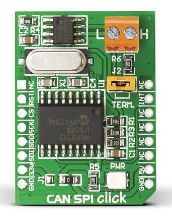
CAN SPI expansion board for ESP32 PLC
CAN SPI Click 5V is a compact add-on board that provides a complete CAN solution and can be used as a control node in a CAN network.
The Controller Area Network (CAN bus) is a standardized vehicle bus
system aimed at facilitating communication between microcontrollers and
devices. Originally developed for multiplex electrical wiring in
automobiles to optimize copper usage, it has found applications across
various domains. CAN bus operates on a message-based protocol where data
within a frame is transmitted serially. In the event of simultaneous
transmissions by multiple devices, priority is given to the highest
priority device, allowing it to continue while others yield. Notably,
frames are received by all devices on the network, including the
transmitting device.
Hardware
To obtain one of our ESP32 PLCs with the CAN board configured, you can
visit our website to view all our products and choose the one that best
suits your needs. Similarly, we also offer all PLCs from the Raspberry
and Arduino families with the option to implement additional
communication through boards.
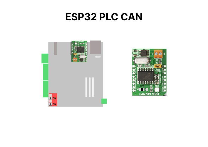
In our ESP32 PLCs, we have two slots for any expansion boards. Expansor 1 is located on the border and Expansor 2 is situated near the Ethernet port. For Expansor 2, set switch 2 and 4 to the ON position to enable the slot.
Software
We have to be sure about which expansor we use to put the CAN SPI click because we have to change some software configuration when executing the test.
For:
- Expansor 1: RSTpin 6, INTpin 5 and pinCS = 32
- Expansor 2: RSTpin 3, INTpin 1 and pinCS = 2
This code uses two libraries:
- The MCP_CAN library is used for interfacing Arduino or similar microcontrollers with MCP2515/MCP25625 CAN controllers, enabling CAN bus communication.
- The Adafruit-MCP23008
library facilitates communication between microcontrollers and MCP23008 GPIO
expanders, enabling easy control of additional digital inputs and
outputs..
Both libraries have been modified from the original ones to enable all features the CAN Click board can offer. Next are both ZIP files, which can be directly imported to Arduino IDE
CAN SPI Test
Here are the test codes for the CAN SPI board compatible with any member
of the ESP32 PLC family. One code is designated for transmission while
the other is for reception.
To conduct the test, you need to download the provided files and upload them onto two separate ESP32 PLCs using Arduino IDE. One PLC will serve as the transmitter, while the other will act as the receiver.
Once the files are uploaded, you'll need to connect the two ESP32 devices via the CAN SPI click module to ensure proper transmission and reception of data.
It's crucial to
consider the hardware configuration, including the switch settings and
the placement of the CAN SPI click board, to determine the pin
configurations and any necessary adjustments.