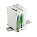
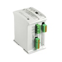
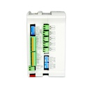
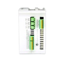
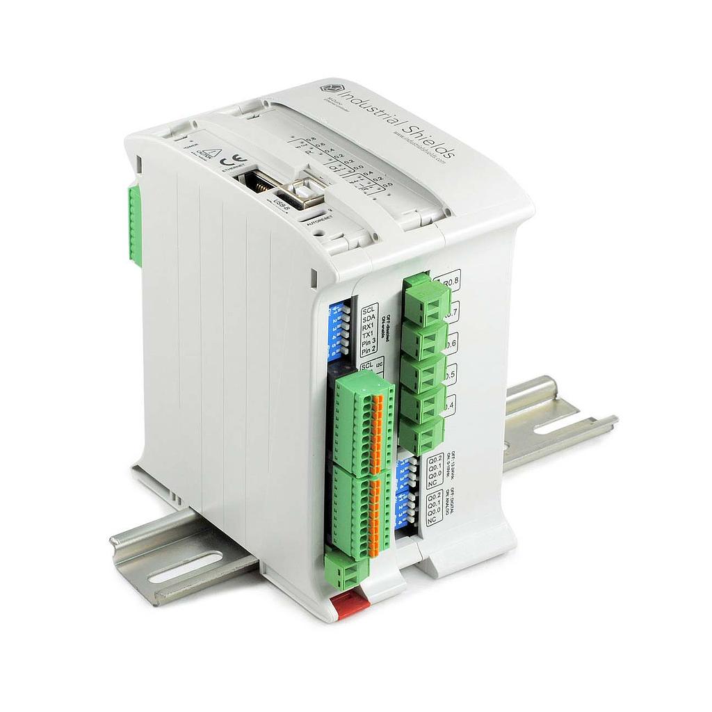
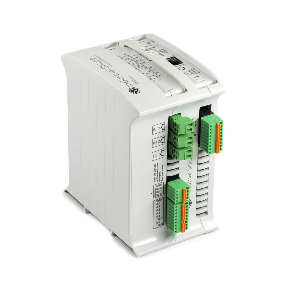
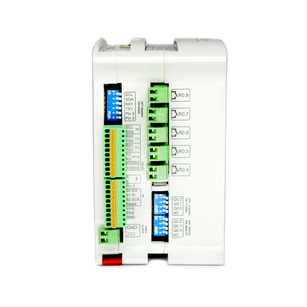
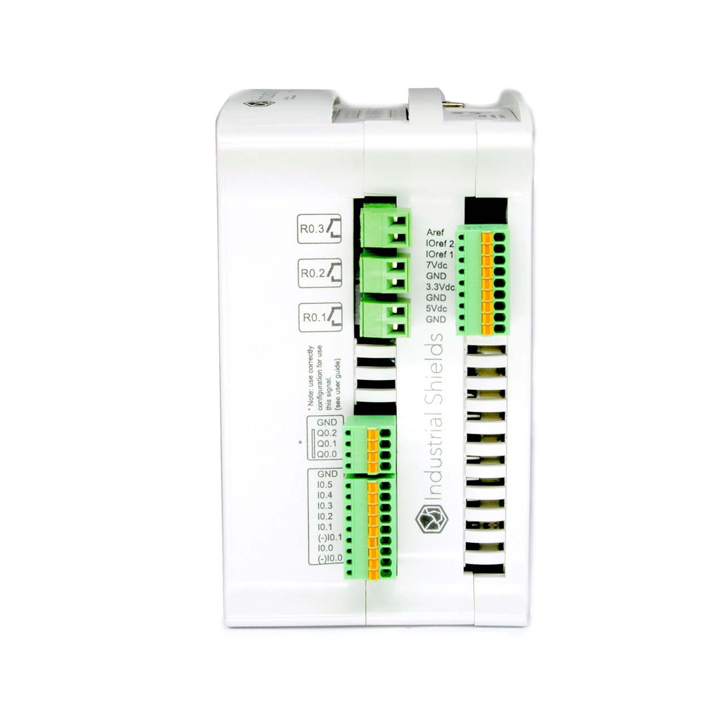
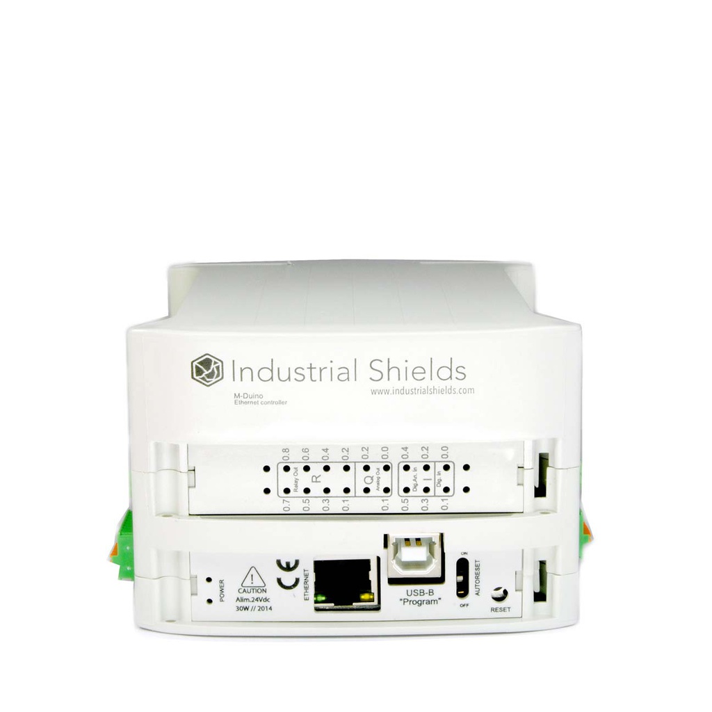
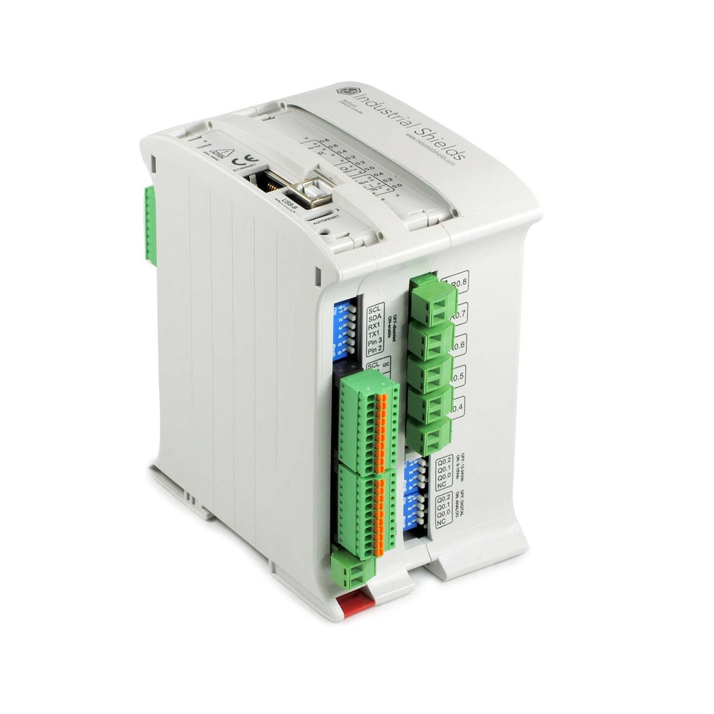
PLC Arduino M-Duino 19R+: 17 E/S con salidas digitales, analógicas y de relé
El M-Duino 19R+ es un PLC industrial compacto basado en el Arduino Mega 2560. Ofrece 17 puntos de E/S: 4 entradas analógicas/digitales convertibles (0 a 10 Vdc), 2 entradas digitales aisladas con capacidad de interrupción, 3 salidas configurables digital/PWM/analógica (0 a 10 Vdc) y 8 salidas de relé. Con Ethernet (W5500), doble RS-485, RS-232, doble Serial TTL, I2C, SPI y un RTC integrado, está pensado para proyectos de automatización, monitorización y adquisición de datos que necesitan control de relés integrado.
Especificaciones técnicas
| Especificación | Valor |
|---|---|
| Número de referencia | IS.MDuino.19R+ |
| Total de E/S | 17 |
| Arquitectura | 2 layers (CR) |
| Microcontrolador | Arduino Mega 2560 |
| Entradas | 6 |
| Entradas analógicas/digitales convertibles (0 a 10 Vdc) | 4 |
| Entradas digitales aisladas (con interrupción) | 2 |
| Salidas | 9 |
| Salidas digital/PWM/analógica (0 a 10 Vdc) | 3 |
| Relay Outputs | 8 |
| Ethernet | Sí (W5500, 10/100 Mbps) |
| Puertos RS-485 | 2 |
| Puertos RS-232 | 1 |
| Puertos Serial TTL / UART | 2 |
| SPI | Yes |
| I2C | Yes |
| RTC | Yes |
| Ranura MicroSD | Yes |
| Alimentación | 12 a 24 Vdc |
| Consumo máximo | 4.848 W |
| Montaje | Carril DIN |
| Certificaciones | CE, RoHS |
Aplicaciones: control de bombas y motores, iluminación y pequeña automatización
El M-Duino 19R+ es adecuado para proyectos de pequeña automatización que necesitan conmutar bombas, motores, iluminación u otras cargas de forma directa, sin añadir módulos de relé externos, además de monitorizar señales analógicas y digitales.
Protocolos: Modbus sobre Ethernet y RS-485, RS-232
La comunicación se realiza mediante Ethernet y RS-485 (2 puertos) para Modbus TCP y Modbus RTU, con RS-232 para dispositivos heredados, además de I2C y SPI para periféricos locales.
Programación: Arduino IDE con librerías de Industrial Shields
Se programa mediante Arduino IDE con el paquete de placas industrialshields. Todas las E/S se referencian por nombre (I0_x, Q0_x, A0_x, R0_x).
PLC Arduino para automatización, monitorización y adquisición de datos
El M-DUINO ETHERNET PLC ARDUINO 19R+ es un controlador compacto y fiable diseñado para aplicaciones industriales como automatización, monitorización y adquisición de datos. Combina la robustez de un PLC industrial con la sencillez de la programación en Arduino IDE, lo que facilita su uso en proyectos de energía, agua, infraestructuras inteligentes y muchos otros.
Entradas, salidas y relés integrados
Este PLC incluye entradas y salidas digitales y analógicas con relés integrados. Esto permite accionar directamente bombas, motores o luminarias sin necesidad de hardware adicional. El beneficio: instalaciones más rápidas, menos cableado y reducción de costes.
Comunicaciones industriales estándar
Ethernet y RS-485 (Modbus) vienen integrados de serie para garantizar una comunicación fluida con redes industriales. Cuando el proyecto requiere mayor conectividad, los módulos de expansión internos amplían las opciones sin necesidad de dispositivos externos.
Programación sencilla con Arduino IDE
Basado en Arduino Mega, el M-DUINO ETHERNET PLC ARDUINO 19R+ se programa mediante Arduino IDE. La puesta en marcha local por USB y la programación remota por Ethernet permiten un despliegue rápido, un mantenimiento sencillo y menos tiempos de parada.
Beneficios para tu aplicación
- Control directo de cargas con relés integrados que ahorran espacio y reducen componentes externos
- Integración sencilla en redes existentes con Ethernet y RS-485
- Menor tiempo de instalación y mantenimiento gracias a la programación intuitiva
- Solución fiable para automatización, monitorización y adquisición de datos en proyectos de energía, agua e infraestructuras inteligentes
- Posibilidad de desarrollos a medida a través de nuestro departamento de I+D para necesidades no estándar
Instalación inicial
Arduino IDE
Arduino IDE es la plataforma original para programar placas Arduino. Esta aplicación multiplataforma está disponible en Windows, macOS y Linux bajo la Licencia Pública General de GNU. Arduino IDE admite la estructuración de código en C y C++. Para programar los PLC basados en Arduino Mega en este entorno, Industrial Shields proporciona un paquete de placas con las librerías y herramientas necesarias.
We recommend using the Legacy Arduino IDE (2.3.X) to program M-Duino based PLCs, although other Arduino compatible software could be used. The Arduino 2.3.X IDE can be downloaded from this link. After downloading and installing the Arduino IDE, install the industrialshields boards package inside the IDE. This can be done by following this tutorial and selecting the industrialshields package in step number 6.
Fuente de alimentación
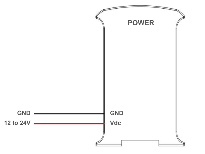
Los PLC basados en M-Duino necesitan alimentarse con una fuente de alimentación externa, con una tensión entre 12 y 24 Vdc. ¡Atención! Aunque a primera vista pueda parecer que el PLC funciona alimentado solo por el puerto USB, no es así. El uso de una fuente de alimentación externa es obligatorio para que el PLC funcione correctamente.
El consumo de los PLC basados en M-Duino oscila entre 700 y 1500 mA. Por ello, Industrial Shields recomienda usar una fuente de alimentación capaz de entregar al menos 2A.
Especificaciones de la fuente de alimentación:
- Tensión: entre 12 y 24 Vdc.
- Intensidad: al menos 2A.
El diagrama de esta sección ilustra las conexiones necesarias para alimentar correctamente un PLC.
Interruptores DIP
Los PLC basados en M-Duino tienen algunos interruptores que se pueden usar para configurar ciertas funcionalidades del PLC. Esta sección explica cómo usarlos correctamente. Para diferenciar las distintas partes del PLC y localizar cada interruptor, se usará la siguiente nomenclatura:
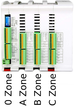
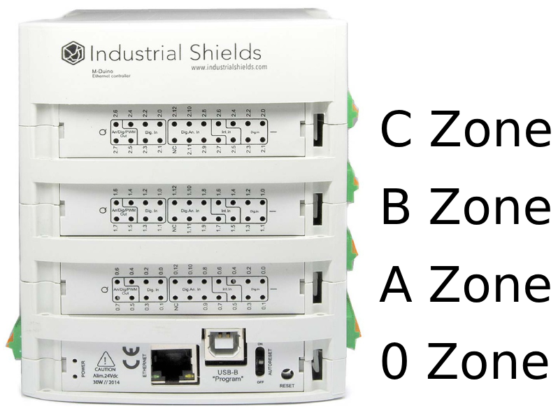
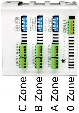
En cada zona hay uno o más interruptores, usados para configurar algunas funcionalidades del PLC. Las siguientes tablas indican la función de cada interruptor y cómo configurarlos.
Zona A: interruptor superior izquierdo
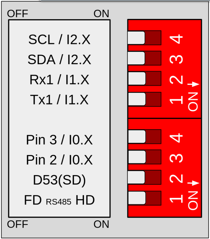
Switch | Off | On |
1 (top) | TX1 | I1.X |
2 (top) | RX2 | I1.X |
3 (top) | SDA | I2.X |
4 (top) | SCL | I2.X |
1 (bottom) | FD | HD |
2 (bottom) | SD | X |
3 (bottom) | Pin 2 | I0.X |
4 (bottom) | Pin 3 | I0.X |
Interruptor superior:
- Si este interruptor está en ON, activa la entrada I1.X y desactiva TX1. Si está en OFF, activa TX1 y desactiva I1.X.
- Si este interruptor está en ON, activa la entrada I1.X y desactiva RX1. Si está en OFF, activa RX1 y desactiva I1.X.
- Si este interruptor está en ON, activa la entrada I2.X y desactiva SDA. Si está en OFF, activa SDA y desactiva I2.X.
- Si este interruptor está en ON, activa la entrada I2.X y desactiva SCL. Si está en OFF, activa SCL y desactiva I2.X.
Interruptor inferior:
- Si este interruptor está en ON, activa la opción Half Duplex (HD) y desactiva el FD. Si está en OFF, activa Full Duplex (FD) y desactiva HD.
- Si este interruptor está en OFF, activa el Chip Select de la tarjeta microSD. En algunos modelos de PLC M-Duino, si está en ON activa una salida digital.
- Si este interruptor está en ON, activa la entrada I0.X y desactiva el Pin 3. Si está en OFF, activa el Pin 3 y desactiva I0.X.
- Si este interruptor está en ON, activa la entrada I0.X y desactiva el Pin 2. Si está en OFF, activa el Pin 3 y desactiva I0.X.
*The X represents different pins for the different M-Duino PLC models.
Zona A: interruptor inferior izquierdo
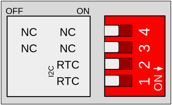
Switch | Off | On |
1 | X | RTC |
2 | X | RTC |
3 | X | X |
4 | X | X |
Solo se usan los interruptores 1 y 2. Ambos interruptores activan la comunicación con el RTC mediante I2C. Con estos interruptores en modo ON se activa esta comunicación, mientras que en modo
OFF se desactiva el I2C para acceder al RTC.
Zona B, C y D: Interruptor analógico
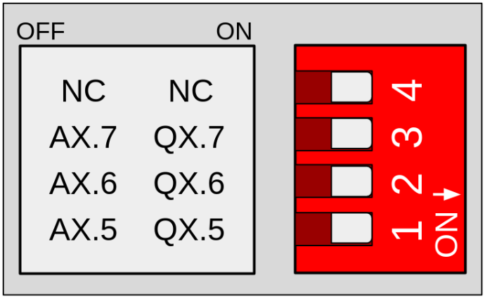
Switch | Off | On |
1 | AX.5 | QX.5 |
2 | AX.6 | QX.6 |
3 | AX.7 | QX.7 |
4 | X | X |
These switches are used to choose between digital or analog output, according to the previous table. If it is set to OFF, only the corresponding analog output will be available. If it is set to ON, only the corresponding digital output will be available. The switches behave the same way in zones B, C and D, with the "X" value being different depending on the zone:
- Zona B: X = 0
- Zona C: X = 1
- Zona D: X = 2
Consumo de energía
Este informe explora cómo consumen energía los distintos modelos de PLC M-Duino
en escenarios de reposo y de salidas al máximo. Entender estos patrones es
clave para optimizar la eficiencia en aplicaciones industriales.
En reposo
En este escenario, el PLC M-Duino está encendido, con todos los pines y comunicaciones apagados y utilizando una fuente de 24V. Esta prueba mide el consumo base cuando el dispositivo está en reposo y no está realizando ningún procesamiento ni salida.
MODEL | CURRENT (mA) | POWER (W) |
| 21+ | 99 | 2,376 |
| 42+ | 92 | 2,208 |
| 58+ | 76 | 1,824 |
| 19R+ | 80 | 1,92 |
| 38R+ | 77 | 1,848 |
| 57R+ | 73 | 1,752 |
| 38AR+ | 72 | 1,728 |
| 53ARR+ | 71 | 1,704 |
| 57AAR+ | 71 | 1,704 |
| 54ARA+ | 76 | 1,824 |
| 50RRA+ | 82 | 1,968 |
Todas las salidas a HIGH
For this test, the M-Duino PLC is configured to set all its output pins to a high state, drawing the maximum current for output operations and utilizing a 24V power supply. This provides insights into the power consumption when the device is actively driving output signals.
MODEL | CURRENT (mA) | POWER (W) |
| 21+ | 120 | 2,88 |
| 42+ | 128 | 3,072 |
| 58+ | 126 | 3,024 |
| 19R+ | 202 | 4,848 |
| 38R+ | 313 | 7,512 |
| 57R+ | 425 | 10,2 |
| 38AR+ | 221 | 5,304 |
| 53ARR+ | 323 | 7,752 |
| 57AAR+ | 221 | 5,304 |
| 54ARA+ | 231 | 5,544 |
| 50RRA+ | 322 | 7,728 |
Entradas y Salidas
Entradas analógicas
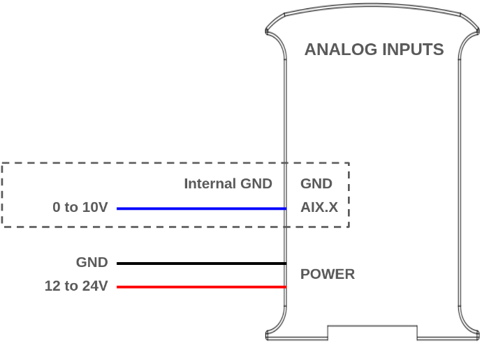
La entrada analógica permite leer niveles de tensión analógicos, codificando el valor con un número de N bits. Las entradas analógicas del PLC basado en M-Duino usan el GND interno como referencia (el mismo que la fuente de alimentación). Las entradas analógicas de estos PLC tienen las siguientes especificaciones:
- Rango de tensión: de 0 a 10 Vc.
- Resolución: 10 bits, lo que significa que los valores leídos pueden oscilar entre 0 y 1023.
Además, las entradas analógicas también se pueden usar como entradas digitales no aisladas, tolerando hasta 24Vdc. Para ello, consulta la sección de entradas digitales. Las entradas analógicas son las que van de IX.7 a IX.12, con X siendo 0, 1 o 2 según la zona. Puedes identificar las entradas analógicas en tu dispositivo con el siguiente símbolo:
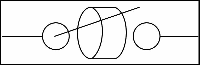
0V - 10Vdc Analog input
The next diagram illustrates the necessary connections to properly use an analog input (when used as a digital, the input can tolerate up to 24V):
Configuración de software
Para usarlas, las entradas analógicas deben configurarse en la parte de setup del código, como se hace habitualmente en placas Arduino comunes. Después se pueden leer usando la función "analogRead()", con el nombre de la entrada como parámetro. Por ejemplo, I0.7 se lee como I0_7:
The following post might also be of interest: Learning the basics about analog inputs of an industrial PLC.
Entradas digitales
Las entradas digitales se usan para capturar señales que existen en uno de dos estados: alto o bajo, verdadero o falso, etc. Las entradas digitales del PLC M-Duino interpretan como valores altos 5 Vdc o superiores, hasta 24 Vdc, mientras que valores inferiores a 5V se interpretan como bajos. Hay 2 tipos de entradas que se pueden usar como entrada digital:
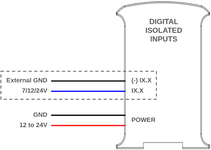
- Digital isolated inputs (5 - 24 Vdc): these inputs are opto-isolated, which means they have an extra protection and they use an external ground pin for reference. They are the pins from IX.0 to IX.6, where X is 0,1 or 2 depending on the zone.
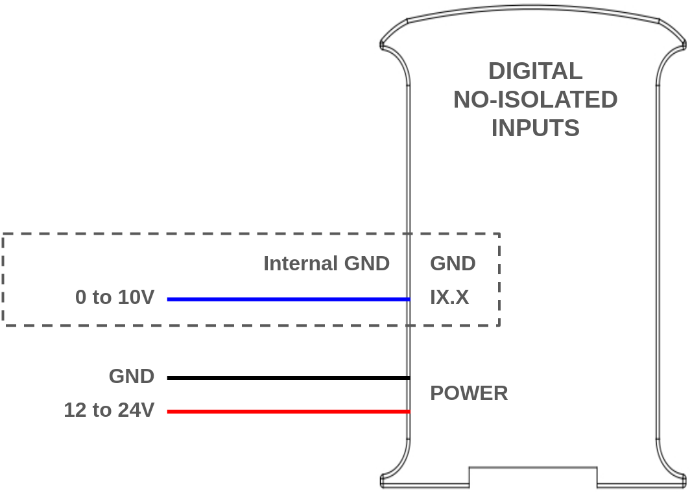
- Entrada digital no aislada (5 - 24 Vdc): estas entradas no están opto-aisladas, y usan el GND interno del PLC como referencia. Son las mismas que las entradas analógicas, de IX.7 a IX.12, con X siendo 0, 1 o 2 según la zona.
Puedes identificarlas con los siguientes símbolos:
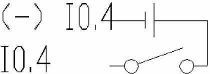
5V - 24V isolated input

5V - 24V non-isolated input
The next diagrams illustrate the necessary connections to properly use both inputs as digital:
Configuración de software
Para usarlas, las entradas digitales deben configurarse en la parte de setup del código, como se hace habitualmente en placas Arduino comunes. Después se pueden leer usando la función "digitalRead()", con el nombre de la entrada como parámetro. Por ejemplo, I0.0 se lee como I0_0:
The following posts expand on this topic: Basics about digital inputs of an industrial controller, PNP Digital Inputs on industrial PLC.
Entradas de interrupción
Algunas de las entradas digitales del PLC M-Duino admiten interrupciones, lo que significa que se pueden usar con ISR (rutina de servicio de interrupción) para ejecutar cierto código cuando se detecta un evento (un cambio de estado en el pin). Hay dos pines de este tipo en cada zona: IX.5 e IX.6. Se usan y conectan como entradas digitales aisladas normales, y las interrupciones se programan por software.
Configuración de hardware
Las entradas de interrupción deben activarse usando los interruptores superiores de la zona A:
- I0.5 e I0.6 también funcionan como Pin3 y Pin2. Activa las interrupciones poniendo en ON los interruptores 3 y 4 inferiores de comunicación.
- I1.5 e I1.6 también funcionan como Tx1 y Rx1. Activa las interrupciones poniendo en ON los interruptores 1 y 2 superiores de comunicación.
- I2.0 e I2.1 también funcionan como SCA y SCL. Activa las interrupciones poniendo en ON los interruptores 3 y 4 superiores de comunicación. En este caso no podrás usar I2C.
Consulta la sección "Instalación inicial - Hardware" de esta página para más información.
Configuración de software
Este es un ejemplo de cómo usar los pines de interrupción. En este caso, la función "isrI0_5()" se llama automáticamente cada vez que ocurre un cambio de estado en el pin I0.5.
Salidas analógicas
An analog output provides a voltage determined by a digital value with an N-bit number. The M-Duino PLCs can have between 3 and 9 analog outputs, depending on the model. These are labeled as AX.X, and need to be selected via DIP switch to be used. Refer to the switch section in this page for more information about the switches. The analog outputs in the M-Duino PLC have the following specifications:
- Rango de tensión: de 0 a 10 Vac.
- Resolution: 8 bits.
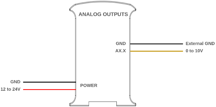
Las salidas analógicas comparten un pin de GND externo, que debe conectarse para fijar la referencia. Este símbolo identifica las salidas analógicas, y el siguiente diagrama ilustra cómo conectarlas:
 0 - 10V analog output
Configuración de software
El procedimiento para programar las salidas analógicas es el mismo que en Arduino habitual: primero, el modo del pin debe fijarse como "OUTPUT" en el setup del código, y después la salida se puede escribir usando "analogWrite()". Las salidas analógicas se referencian por su nombre usando un "_" en vez del ".". Por ejemplo, A0.5 se usa como A0_5:
To know more about analog outputs: Basics about analog outputs of an industrial PLC.
Digital outputs
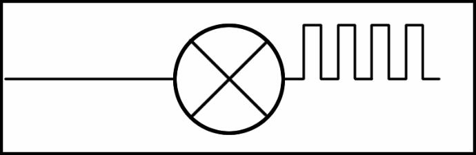
Las salidas digitales del PLC M-Duino pueden dar un valor bajo (0 Vdc) o alto (hasta 24 Vdc). Estas salidas se etiquetan como QX.X, y se pueden identificar con el siguiente símbolo.
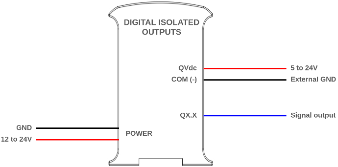
The output high value can range between 5 and 24 Vdc. This voltage needs to be set using two pins located next to the outputs: QVdc and COM(-). For instance, should you wanna set the output to 24V, the QVdc pin should be connected to 24V and the COM(-) pin to GND. The following diagram illustrates an example connection:
Digital output (PWM optional)
Configuración de software
Las salidas digitales deben configurarse en la parte de setup del código como se hace habitualmente en placas Arduino comunes, usando primero "pinMode()" para fijarla como "OUTPUT", y "digitalWrite()" para cambiar el valor de la salida. Consulta el siguiente ejemplo:
You can learn more about digital outputs in this post: Basics about digital outputs of an industrial PLC.
Salida PWM
In the M-Duino based PLCs, some of the digital outputs can be used as PWM outputs.
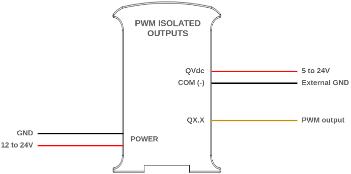
El valor alto de la salida puede oscilar entre 5 y 24 Vdc. Igual que cuando se usan como salidas digitales simples, esta tensión debe fijarse usando dos pines situados junto a las salidas: QVdc y COM(-). Por ejemplo, si quieres fijar la salida a 24V, el pin QVdc debe conectarse a 24V y el pin COM(-) a GND. El siguiente diagrama ilustra un ejemplo de conexión.
An example tutorial about how to program the PLC to use the PWM outputs can be found in our repository using the avr-Pulses library.
PWM capable output
Salida de relé
A relay is an electromagnetic switch controlled by an electric signal. In Industrial Shields units these devices are already integrated in their boards. The relays included in the M-Duino PLC can work up to 24 Vdc or 220 Vac. Each relay output has two terminals, and is labelled as RX. The following diagram illustrates the connections:
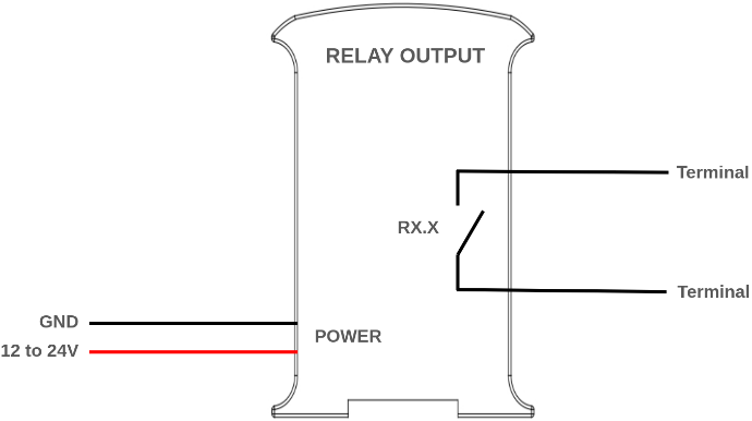
Configuración de software
La salida de relé debe configurarse en la parte de setup del código, usando funciones de Arduino, y se controlan como si fueran salidas digitales. Las salidas se referencian por el nombre indicado en la serigrafía: R0.1, por ejemplo, se usa como R0_1. Consulta el siguiente ejemplo. Cuando la salida se pone en "HIGH", el relé se activa, es decir, el contacto se cierra, mientras que en "LOW" el contacto se abre.
To know more about the relay outputs, check out this post: Learning the basics about internal relays of an industrial PLC.
Comunicaciones
Ethernet
Ethernet is the most commonly used technology in wired local area networks ( LANs ).
A LAN is a network of computers and other electronic devices that covers a small area such as a room, office, or building. It is used in contrast to a wide area network (WAN) , which spans much larger geographical areas. Ethernet is a network protocol that controls how data is transmitted over a LAN. Technically it is referred to as the IEEE 802.3 protocol. The protocol has evolved and improved over time to transfer data at the speed of a gigabit per second.
The M-Duinos PLCs incorporate an Ethernet port, using the W5500 controller, which communicates with the Arduino using SPI. The W5500 is a Hardwired TCP/IP embedded Ethernet controller that provides easier Internet connection to embedded systems. This chip enables users to have Internet connectivity in their applications by using the single chip in which TCP/IP stack, 10/100 Ethernet MAC and PHY are embedded. With this chip users can integrate Ethernet into their applications.
Configuración de software
The Industrial Shields boards package includes an "Ethernet" library, intended to facilitate the use of this protocol. Various examples are included with the library, you can check them out going to File > Examples > Ethernet inside the Arduino IDE.
Also take a look at the following program. Before running the code, ensure that your PLC is powered correctly, confirm that the Ethernet cable is securely connected to your device and make sure the "industrialshields" board package is properly installed in your Arduino IDE. This code serves as a diagnostic tool to ensure the proper functioning of the Ethernet port. It establishes a connection to "www.google.com" through the W5500 controller using DHCP IP configuration.
RS-485
RS485, also known as TIA-485(-A), EIA-485, is a standard defining the electrical characteristics of drivers and receivers for use in serial communications systems.The M-Duino PLCs include half-duplex RS485 capabilites, thanks to the incorporated MAX485 transceiver chip.
El MAX485 es un transceptor de bajo consumo y slew-rate limitado usado para comunicación RS-485. Funciona con una única alimentación de +5V y su corriente nominal es de 300 μA. Al adoptar comunicación half-duplex para convertir nivel TTL a nivel RS-485, puede alcanzar una tasa de transmisión máxima de 2,5 Mbps. El transceptor MAX485 consume entre 120 μA y 500 μA en condiciones sin carga o a plena carga cuando el driver está desactivado.
If you want to know more about RS485, check out this post.
Configuración de hardware
Para usar el RS485 con los PLC M-Duino, revisa el interruptor superior izquierdo de la zona A. El RS485 siempre está activo, pero hay un interruptor (número 1) para elegir entre half-duplex y full-duplex. Para más información sobre los interruptores, consulta la sección "Instalación inicial - Hardware" de esta página.
The RS485 pins, A+ and B- need to be properly connected to the device the PLC is communicating with. Attention! Remember to properly power the PLC with a 12-24V power supply.
Configuración de software
Our boards package includes an RS485 library to make programming easier. This library is used as the Arduino Serial library, with methods such as "available()", "read()", etc.
Check out the following code, which establishes half duplex communication and allows the user to read or send messages from the terminal of the PC.
RS232
RS-232 is a standard for serial communication transmission of data. It formally defines the signals used in communication between DTE (Data Terminal Equipment) such as a computer terminal, and DCE (Data Circuit-terminating Equipment or Data Communication Equipment), such as a modem. The M-Duino PLC includes a MAX232 transceiver chip, allowing full-duplex communication through RS232. The MAX232 is a dual transmitter/dual receiver that is used to convert the RX, TX, CTS, RTS signals, converting signals from Serial TTL to TIA-232 (RS-232) serial port.
If you want to know more about RS232, check this post.
Configuración de hardware
The RS232 pins, TX and RX need to be properly connected to the device the PLC is communicating with. Attention! Remember to properly power the PLC with a 12-24V power supply.
Configuración de software
Once the hardware configuration is done, it is possible to proceed with the software configuration and its usage. Firstly, it is necessary to include the RS232.h library provided by our boards package. Then, the communication must be initialized with "RS232.begin(<baudrate>);". After this RS232 can already be used with the functions "RS232.read();" and "RS232.write();".
Consulta los siguientes ejemplos de lectura y escritura:
Serial TTL
Serial TTL is a communication Interface between two devices with working at a low level voltage. Two signals are used: Tx (Transmit Data) and Rx (Receive Data), which allow full-duplex communication. The M-Duino PLCs have two external TTL ports, Serial 1 (RX1/TX1) and Serial 0 (RX0/TX0).
To know more about the serial TTL interface, visit this blog.
Configuración de hardware
The M-Duino PLC features two serial ports. One of them, the Serial 1 (TX1, RX1), needs to be activated using the A zone top left switch. For more information about the switches, check the "Initial installation - Hardware" section in this page.
For the Serial communication to work, the following connections between the PLC and the other device need to be made:
- TX -> RX
- RX -> TX
- GND, both devices need to share a common ground.
Attention! The M-Duino PLCs serial ports work at 5V levels. Higher voltage levels might damage the PLC.
Also, remember to properly power the PLC with a suitable 12-24Vdc power supply.
Configuración de software
In order to use the Serial communication with the PLC, the Arduino "Serial" object can be used. Check the following example, which uses Serial 1, to send and receive byte using the USB serial port and the Serial 1. To use the Serial 2 instead of the 1, the "Serial2" object must be used.
I2C
I2C is a serial communications protocol. It is a master-slave synchronous protocol and 2 cables are used, one for the clock (SCL) and one for the data (SDA).
The master controls the bus and creates the clock signal, and uses addressing to communicate with the slaves. It is a very used bus in the industry, mainly to
communicate microcontrollers and their peripherals in integrated
systems, normally located in the same PCB. The speed is 100 Kbit/s in standard mode.
Configuración de hardware
The M-Duino PLCs have one I2C port, with the SCL and SDA pins. These pins need to be activated using the A zone top left switch (SCL and SDA need to be selected in switches 3 and 4). For more information about the switches, check the "Initial installation - Hardware" section in this page.
Other devices can be connected to this bus as slaves. When connecting other devices, keep in mind the following specifications:
- The I2C port works at 5V. Higher voltage levels might damage the PLC.
- The I2C pins, SCL and SDA, are pulled up to 5V.
Also, remember to properly power the PLC with a suitable 12-24Vdc power supply.
Software Setup
The I2C can be used with the library "Wire". Check the following example which implements an I2C scanner that searches the bus for any connected devices. When a device is detected, it will be reported to the serial monitor. Note that if you connect the I2C pins (SDA and SCL) to an other device, it should appear in the scan.
Before running the code, ensure that your PLC is powered correctly, verify that the "industrialshields" board package is correctly installed in your Arduino IDE and that you have selected the correct PLC model inside your IDE.
SPI
The Serial Peripheral Interface (SPI) is a synchronous serial communication interface specification used for short-distance communication, primarily in embedded systems. SPI devices communicate in full duplex mode using a master-slave architecture, usually with a single master. 3 pins are used with SPI communication: SCLK, MOSI, MISO. Additionally, one extra pin for each slave, called chip select (CS) or slave select (SS) is used to select the slave that is being talked to in the bus.
The M-Duino PLC features one SPI port.
Configuración de hardware
In order to use the SPI, the 3 mention pins (SCLK, MISO, MOSI) must be properly connected:
Function | M-Duino PLC Pin | Arduino Mega Pin |
MISO | SO | 50 |
MOSI | SI | 51 |
CLOCK | SCK | 52 |
RST | Reset | Reset |
Attention! The SPI works at 5V voltage levels, any higher voltage might damage the PLC.
Also, remember to properly power the PLC with a suitable 12-24Vdc power supply.
Configuración de software
The "industrialshields" boards package includes an SPI library, based on the Arduino SPI library. This library allows programming the MDuino as an SPI master.
This program shows how to set up the MDuino
as a master in SPI communication, and send and receive data. In this
case the character "0" is sent, and the received data is stored in the
corresponding variable (SPI transfer is based on a simultaneous send and
receive) and printed through the serial port.
To know more about SPI check the following post: Bus SPI on PLC Arduino from Industrial Shields
Características adicionales
RTC
RTC stands for Real Time clock, en electronic device that measures the passage of time. Although keeping time can be done without an RTC, using one has benefits such as:
- Mantaining the time without needing to set ti again after a reboot, shutdown, etc.
- Low power consumption (important when running from alternate power.
- Frees the main control system for time-critical tasks.
- Sometimes more accurate than other methods.
The M-Duino PLC include a DS1307 RTC module, which communicates with the Arduino microcontroller using I2C. The DS1307 serial real-time clock is a lowpower, full binary-coded decimal (BCD) clock/calendar, including 56 bytes of NV SRAM. Iprovides seconds, minutes, hours, day, date, month, and year information.
In order to power the RTC when the PLC is not connected, the PLC includes a 3,3V lithium coin cell battery which can be used to supply the RTC.
No hardware setup is needed in order to use the RTC, the only requirement is for the PLC to be properly powered using a 12-24Vdc power supply, and to have a lithium coin cell battery to maintain the time when the PLC has no power.
Configuración de software
The RTC library, included with our boards package, can be used to interact with the RTC. Check the following code example where time is read from the RTC and printed to the serial monitor.
Remember to make sure you have the industrialshields board package properly installed in your Arduino IDE.
SD
Secure Digital (SD) cards are non-volatile memory storage devices that
use flash memory technology. Designed for portable electronic devices,
SD cards provide a reliable and compact solution for data storage.
The M-Duino PLC incorporates an SD card slot with the following specifications:
- MicroSD slot.
- Up to 32GB of storage (although higher capacity cards can be used, only the first 32GB will be accessible and usable).
- FAT32 and FAT16 allowed as file system architectures.
The SD slot communicates with the M-Duino using SPI, and there is no hardware configuration needed. Remember to power the PLC with a proper 12-24Vdc power supply.
Configuración de hardware
In order to use the SD with the M-Duino PLCs, check the A zone top left
switch. For more information about the switches, check the "Initial
installation - Hardware" section in this page.
Configuración de software
The "industrialshields" boards package includes an SD library to facilitate its usage. Check the following example, which initializes the SD card and prints the contents of it root directory through the serial port.
Pines directos de Arduino
If we want to use another Serial Port using this equipment, we can make use of some digital pins to create a Serial. The SoftwareSerial library has been developed to allow serial communication on other digital pins of the Arduino, using software to replicate the functionality. It is possible to have multiple software serial ports with speeds up to 115200 bps. A parameter enables inverted signaling for devices which require that protocol.
Only I/O 5V from Ardbox or M-Duino boards can be used.
| M-Duino Pins | Ardino Mega Pins |
| MISO | 50 |
| MOSI | 51 |
| SCK | 52 |
Señales de 5 Vdc
These pins can be programmed according to Arduino features such as I/Os operating at 5V or any additional features present in the pins.
- I2C Pins – SDA/SCL: The I2C protocol is meant to work in a pull-up configuration. In this case it reads 5V when nothing is connected.
- Serial 0 – RX0/TX0: The Serial0 protocol can work also as a 5V pin. If using these pins, the USB communication cannot be working at the same time.
- Serial 1 – RX1/TX1: The Serial1 protocol can work also as a 5V pin. Always enabled.
- SPI – MISO/MOSI/SCK: These pins can only work as a 5V pins if the Ethernet protocol is not going to be used. As the Ethernet protocol uses the SPI to communicate with the Arduino board, both behaviors cannot happen at the same time as the Ethernet would not work.
- Pin2/Pin3: These pins are only referred to the inputs I0.5/I0.6. If the switch configuration is in OFF position the pins Pin 2/Pin 3 will be available.
Productos alternativos
Estos productos podrían interesarle