
Introduction
In this post, we aim to explore how to achieve an efficient sending and receiving communication while actually dealing with a half-duplex setup. Our goal is to facilitate DE/RE communication, enabling simultaneous sending and receiving through software. In the forthcoming examples, we will explore a method to handle the process. While it may not involve sending and receiving at the exact moment, we aim to manage it in a way that, automatically after sending, the device switches to listening mode, anticipating a potential incoming data.
UPSafePi RS485
This device consists of a Raspberry Pi 4 connected to a UPS & RTC shield, all enclosed in a perfectly fitted casing.
In order to focus on its RS485 communication, certain aspects need to be considered:
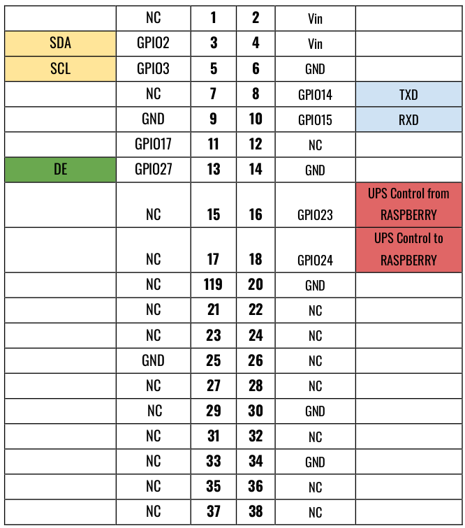
- Cables for the RS485 communication between the two devices will be connected to pins 16 and 18. These pins are under the UPS control.
- Pin 13 is assigned to GPIO27, which serves as the 485 half-duplex control. Transmission is enabled with a positive logical value, while reception is enabled with a negative logical value.
In the following image, we see how the pin management is distributed, and indeed, there is only one pin for this half-duplex communication. That's why there is no RE instead, it's the same pin as DE but negated.
For more information about UPSafePI, click here.
Example codes
For this example there is used a UPSafePI and a Raspberry PI PLC 21+. Keep in mind that this test can be implemented with another device with RS-485 instead of the Raspberry PI PLC just by connecting the RS-485 ports with each other (A-A and B-B). For the implementation of this example you will need some python3 libraries:
- serial: This library provides a way to interact with serial ports on your system. In this code, it is used to configure and manage communication over the serial port, specifically the RS485 communication. The Serial class from this library is used to set up the serial port parameters such as port name ('/dev/ttyS0'), baudrate (9600), and timeout (1 second).
- RPi.GPIO: This library is used for General Purpose Input/Output (GPIO) operations on a Raspberry Pi. It allows you to configure and control the GPIO pins on the Raspberry Pi board. In this code, it is used to set up and control the GPIO pin (27) connected to the DE/RE pin of the RS485 interface.
- time: This is a standard Python library that provides various time-related functions. In this code, it is used to measure the time taken for the transmission and reception of data. The time.time() function is used to get the calculation of the time spend to send and receive the data.
This first code is for the UPSafePI device. This program sends some data using the RS-484 communication and receives a response, calculating the sending and receiving time. Note that the DE signal (GPIO27) is set HIGH when sends data and LOW when receives it.
import serial
import RPi.GPIO as GPIO
import time

GPIO.setwarnings(False)

# Set GPIO mode to BCM
GPIO.setmode(GPIO.BCM)

# Set the GPIO pin
gpio_pin = 27
GPIO.setup(gpio_pin, GPIO.OUT)

# Set the GPIO pin to low
GPIO.output(gpio_pin, GPIO.LOW)

# Define RS485 parameters
ser = serial.Serial(
        port='/dev/ttyS0',  # Replace with the actual serial port used by your RS485 adapter
        baudrate=9600,
        timeout=1
)

# Function to send data
def send_data(data):
        GPIO.output(gpio_pin, GPIO.HIGH)

        start_time = time.time()

        ser.write(data.encode('utf-8'))
        #time.sleep(0.05)

        end_time = time.time()

        elapsed_time = end_time - start_time
        print("-------------------------------------------------")
        print(f"Tx time: {elapsed_time} seconds")

        # Sleep to send all data
        time.sleep(0.1)

        GPIO.output(gpio_pin, GPIO.LOW)

# Function to receive data
def receive_data():
        GPIO.output(gpio_pin, GPIO.LOW)
        data = ser.readline().decode('utf-8')
        if data:
                print(f"Received data: {data.strip()}")

i = 0

while True:
	data_to_send = f"Message {i}"
	i += 1

	# Send data
	send_data(data_to_send)

	# Do things
	time.sleep(1)

	start_time = time.time()

	# Receive data
	receive_data()

	end_time = time.time()

	elapsed_time = end_time - start_time
	print(f"Rx time: {elapsed_time} seconds")

ser.close()
In case you are using a Raspberry PI PLC as the other device, load this following code. This code simply waits to receive the data from the UPS and sends back a response. In this case there is used /dev/ttySC0 port, remember to change it according to your specifications.
import serial

# Define RS485 parameters
ser = serial.Serial(
        port='/dev/ttySC0',  # Replace with the actual serial port used by your RS485 adapter
        baudrate=9600,
        timeout=1
)

# Function to send data
def send_data(data):
        ser.write(data.encode('utf-8'))

# Function to receive data continuously
def receive_data():
        data = ser.readline().decode('utf-8')
        if data:
                print(f"Received data: {data.strip()}")
                return True
        return False

i = 0

while True:
        # Receive data
        if receive_data():
                data_to_send = f"Received {i}"
                i += 1
                # Send data
                send_data(data_to_send)

ser.close()