Introducción
Modbus es el protocolo de comunicaciones más utilizado en la automatización industrial y de edificios y el medio más común para conectar dispositivos electrónicos automatizados.
Aprovechando esto, aprendiste a conectar un sensor de temperatura Dallas DS18B20. También obtuviste la temperatura del sensor Dallas a tu PLC basado en Arduino.
Y ahora, vas a conectarlo a través de Modbus con un Touchberry Pi 10.1", un panel PC de Raspberry Pi, y hacer un panel de control muy simple con Node-RED.
Últimas publicaciones
Conexiones
.jpg?access_token=6f195a22-7cea-4922-9bb8-3d274ad3e11a)
Explicación
Lectura de registros de entrada
Modbus basa su modelo de datos en una serie de tablas que tienen características distintivas. Las cuatro tablas principales son:
| TABLAS PRIMARIAS | TIPO DE OBJETO | TIPO DE | COMENTARIOS |
| Entradas discretas | Un solo bit | Solo lectura | Este tipo de datos se proporcionan a través de un sistema de E/S.. |
| Coils | Un solo bit | Lectura-Escriptura | Este tipo de datos pueden ser alterados por una aplicación. |
| Registros de entrada | 16-bit word | Solo lectura | Este tipo de datos se proporcionan a través de un sistema de E/S. |
| Registros holding | 16-bit word | Lectura-Escriptura | Este tipo de datos pueden ser alterados por un programa de aplicación.. |
Las distinciones entre entradas y salidas, y entre elementos de datos direccionables por bits y por palabras, no implican ningún comportamiento de la aplicación. Es perfectamente aceptable, y muy común, considerar las cuatro tablas como superpuestas. Para cada una de las tablas primarias, el protocolo permite la selección individual de 65536 elementos de datos, y las operaciones de lectura o escritura en esos elementos están diseñadas para abarcar múltiples elementos de datos consecutivos hasta un límite de tamaño de datos que depende del código de función de la transacción.
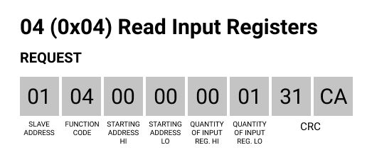
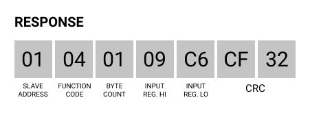
En este post, vamos a centrarnos en el código de función (FC) número 4, que tiene la siguiente estructura de trama:
- Requisito:
- Dirección del esclavo (1 byte),
- FC (1 byte)
- Dirección inicial (2 bytes: de 0x0000 a 0xFFFF)
- Cantidad de registros de entrada (2 bytes: from 0x0001 to 0x007D)
- CRC
- Respuesta:
- Dirección del esclavo (1 byte)
- FC (1 byte: 0x04)
- Recuento de bytes (1 byte: 2 x N*)
- Registros de entrada (N* x 2 bytes)
- CRC
En Node-RED, se enviará una petición; se ejecutará un script que procesará la información para obtener una respuesta con la temperatura de tu sensor de temperatura Dallas DS18B20 conectado a un PLC basado en Arduino.

Ahora, añade un nodo inject y escribe esta trama en una cadena msg.payload como se muestra en el golpe de imagen. A continuación, cabléalo a un nodo exec donde se llamará a un script para procesar la información.

Ahora, copia este script a su Touchberry Pi 10.1" industrial Panel PC y nómbralo como quieras, como modbus.c, también recuerda que debes establecer la tasa de RS-485 a 9600UL..
// C library headers
#include <stdio.h>
#include <string.h>
// Linux headers
#include <fcntl.h> // Contains file controls like O_RDWR
#include <errno.h> // Error integer and strerror() function
#include <termios.h> // Contains POSIX terminal control definitions
#include <unistd.h> // write(), read(), close()
#include <stdlib.h>
#include <sys/stat.h>
#include <dirent.h>
#include <errno.h>
///////////////////////////////////////////////////////////////////////////////////////
// Convert char to int
int char2int(char input)
{
  if(input >= '0' && input <= '9') {
    return input - '0';
  }
  if(input >= 'A' && input <= 'F') {
    return input - 'A' + 10;
  }
  if(input >= 'a' && input <= 'f') {
    return input - 'a' + 10;
  }
  return 0;
}
///////////////////////////////////////////////////////////////////////////////////////
void hex2bin(const char* src, char* target)
{
  while(*src && src[1])
  {
    *(target++) = char2int(*src)*16 + char2int(src[1]);
    src += 2;
  }
}
///////////////////////////////////////////////////////////////////////////////////////
int main(int argc, char* argv[]) {
  char read_buf [256];
  int fd;
  if (argc < 2) {
    printf("Usage: %s <data-hex>\n", argv[0]);
    return 1;
  }
  char buf[100];
  hex2bin(argv[1], buf);
  int buflen = strlen(argv[1]) / 2;
  // Open the serial port. Change device path as needed (currently set to an standard FTDI USB-UART cable type device)
  int serial_port = open("/dev/ttyS0", O_RDWR);
  // Create new termios struc, we call it 'tty' for convention
  struct termios tty;
  // Read in existing settings, and handle any error
  if(tcgetattr(serial_port, &tty) != 0) {
      printf("Error %i from tcgetattr: %s\n", errno, strerror(errno));
      return 1;
  }
  tty.c_cflag &= ~PARENB;
 // tty.c_cflag &= ~PARODD; // Clear parity bit, disabling parity (most common)
  tty.c_cflag &= ~CSTOPB; // Clear stop field, only one stop bit used in communication (most common)
  tty.c_cflag &= ~CSIZE; // Clear all bits that set the data size
  tty.c_cflag |= CS8; // 8 bits per byte (most common)
  tty.c_cflag &= ~CRTSCTS; // Disable RTS/CTS hardware flow control (most common)
  tty.c_cflag |= CREAD | CLOCAL; // Turn on READ & ignore ctrl lines (CLOCAL = 1)
  tty.c_lflag &= ~ICANON;
  tty.c_lflag &= ~ECHO; // Disable echo
  tty.c_lflag &= ~ECHOE; // Disable erasure
  tty.c_lflag &= ~ECHONL; // Disable new-line echo
  tty.c_lflag &= ~ISIG; // Disable interpretation of INTR, QUIT and SUSP
  tty.c_iflag &= ~(IXON | IXOFF | IXANY); // Turn off s/w flow ctrl
  tty.c_iflag &= ~(IGNBRK|BRKINT|PARMRK|ISTRIP|INLCR|IGNCR|ICRNL); // Disable any special handling of received bytes
  tty.c_oflag &= ~OPOST; // Prevent special interpretation of output bytes (e.g. newline chars)
  tty.c_oflag &= ~ONLCR; // Prevent conversion of newline to carriage return/line feed
  // tty.c_oflag &= ~OXTABS; // Prevent conversion of tabs to spaces (NOT PRESENT ON LINUX)
  // tty.c_oflag &= ~ONOEOT; // Prevent removal of C-d chars (0x004) in output (NOT PRESENT ON LINUX)
  tty.c_cc[VTIME] = 1;    // Wait for up to 1s (10 deciseconds), returning as soon as any data is received.
  tty.c_cc[VMIN] = 0;
  // Set in/out baud rate to be 9600
  cfsetispeed(&tty, B9600);
  cfsetospeed(&tty, B9600);
  // Save tty settings, also checking for error
  if (tcsetattr(serial_port, TCSANOW, &tty) != 0) {
      printf("Error %i from tcsetattr: %s\n", errno, strerror(errno));
      return 1;
  }
// Export the desired pin by writing to /sys/class/gpio/export
  int dir = open("/sys/class/gpio/gpio27", O_WRONLY);
  if (ENOENT == errno) {
    /* Directory does not exist. */
//    write(dir, "27", 2);
    fd = open("/sys/class/gpio/export", O_WRONLY);
    if (fd == -1) {
      perror("Unable to open /sys/class/gpio/export");
      exit(1);
    }
    if (write(fd, "27", 2) != 2) {
      perror("Error writing to /sys/class/gpio/export");
      exit(1);
    }
  }
  close(dir);
// Set the pin to be an output by writing "out" to /sys/class/gpio/gpio27/direction
  fd = open("/sys/class/gpio/gpio27/direction", O_WRONLY);
  if (fd == -1) {
      perror("Unable to open /sys/class/gpio/gpio27/direction");
      exit(1);
  }
  if (write(fd, "out", 3) != 3) {
      perror("Error writing to /sys/class/gpio/gpio27/direction");
      exit(1);
  }
  close(fd);
  fd = open("/sys/class/gpio/gpio27/value", O_WRONLY);
  if (fd == -1) {
      perror("Unable to open /sys/class/gpio/gpio27/value");
      exit(1);
  }
  // Toggle LED 50 ms on, 50ms off, 100 times (10 seconds)
  if (write(fd, "1\n", 2) != 2) {
    perror("Error writing to /sys/class/gpio/gpio27/value");
    exit(1);
  }
  //usleep(10000);
///////////////////////////////////////////////////////////////////////////////////////////////////////////////////////////////
  if (write(serial_port, buf, buflen) < 0) {
	perror("Error writing to serial port");
	exit(1);
  }
int t = 10 * buflen * 1000000 / 9600;
usleep(t);
usleep(1000);
//tcdrain(serial_port);
///////////////////////////////////////////////////////////////////////////////////////////////////////////////////////////////
  if (write(fd, "0\n", 2) != 2) {
    perror("Error writing to /sys/class/gpio/gpio27/value");
    exit(1);
  }
  usleep(5000);
  close(fd);
  // Normally you wouldn't do this memset() call, but since we will just receive
  // ASCII data for this example, we'll set everything to 0 so we can
  // call printf() easily.
  //memset(read_buf, '\0', sizeof(read_buf));
  // Read bytes. The behaviour of read() (e.g. does it block?,
  // how long does it block for?) depends on the configuration
  // settings above, specifically VMIN and VTIME
//  char* num_bytes[] = {};
//  for (int i = 0; i < sizeof(read_buf); i++){
//    num_bytes[i] = read_buf[i];
//  }
char c;
int n;
char* ptr = read_buf;
int num_bytes = 0;
do {
	n = read(serial_port, &c, 1);
	if (n < 0) {
		perror("Read  serial port fail");
		exit(1);
	} else if (n > 0) {
		*ptr++ = c;
		++num_bytes;
	}
} while (n > 0);
  // n is the number of bytes read. n may be 0 if no bytes were received, and can also be -1 to signal an error.
  if (num_bytes < 0) {
      printf("Error reading: %s", strerror(errno));
      return 1;
  }
// Here we assume we received ASCII data, but you might be sending raw bytes (in that case, don't try and
// print it to the screen like this!)
// for (int i = 0; i < num_bytes; i++) {
//  printf("Read %i bytes. Received message: %s", num_bytes, read_buf);
// }
//  for (int i = 0; i < num_bytes; i++){
//  printf("Read %i bytes. Received message: %s", num_bytes, read_buf);
//  }
//printf("Received buffer (%d): ", num_bytes);
  for (int i = 0; i < num_bytes; ++i) {
    printf("%02x", read_buf[i]);
  }
  printf("\n");
  close(serial_port);
  return 0; // success
}
///////////////////////////////////////////////////////////////////////////////////////
Luego, en el nodo exec, vas a ejecutar el archivo binario modbus que acabas de compilar. Agrega el comando para llamar al archivo en la ruta que pusiste y anexa el msg.payload con la trama para ejecutar el script con un parámetro:

Tras ejecutar el script, la respuesta que obtuvimos fue: 01040109C6CF32. Entonces, analicemos la trama:

Lo que realmente importa, los datos que te interesan, son los registros de entrada, así que 09C6. Así que vamos a obtenerlo con un nodo de función y convertirlo a decimal, para obtener la temperatura.
Ahora, añade un nodo de función con el siguiente código:
var temp = msg.payload;
return {
    payload: parseInt(temp.substring(6,10), 16)/100
}write about products or services here, write about solutions.
En la función anterior, el parseInt con base 16 indica una conversión a Hexadecimal. Debes hacerlo solo obteniendo la subcadena del 6 al 10, es decir, los datos de la trama. Luego, lo divides por 100 ya que enviamos un dato uint16_t desde el código de Arduino.

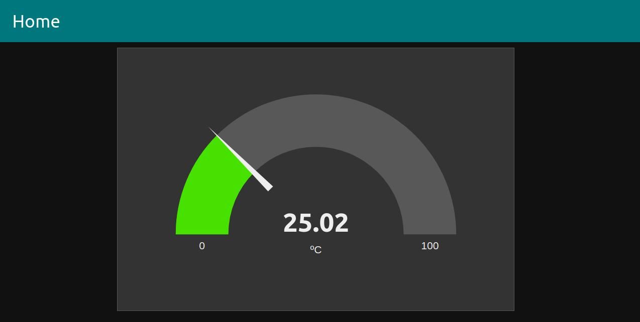
Añade un nodo de depuración o un nodo Dashboard Gauge y comprueba la temperatura mediante Modbus.

Tutorial de Node-RED y Touchberry: Cómo obtener la temperatura del sensor Dallas