

Introduction
In this guide, we will walk you through the steps to verify and configure the Wi-Fi functionality of your ESP32 PLC. Using a simple example available in the Arduino IDE, you'll learn how to establish a network connection, interact with a server, and send HTTP requests. This approach will help you ensure that your setup is working correctly and prepare you to develop more advanced applications.
To follow along, you will need both hardware and software components, as detailed in the requirements section below. Once everything is set up, you’ll be able to test and confirm the PLC's connectivity by monitoring the results through the Serial Monitor.
Requirements
Hardware
- 1 x ESP32 based PLC
- Power supply (12 - 24V)
- micro B type cable, to program the ESP32 based PLC
Software
Verification test
To ensure that the Wi-Fi connection on your ESP32 PLC is properly configured, you can use one of the examples provided in the Arduino IDE. Navigate to File > Examples > WiFi and select one of the available Wi-Fi examples. For this guide, we will use the WiFiClient example.
This sketch connects to a specified Wi-Fi network, establishes a TCP connection to data.sparkfun.com on port 80, and sends a GET request containing data such as a stream ID, a private key, and an incrementing value. The server's response is read and displayed on the Serial Monitor, allowing you to verify that the connection and data transmission are working correctly.
How It Works
- Wi-Fi Connection:
- The setup() function connects to the Wi-Fi network using the provided SSID and password. The device's IP address is printed to the Serial Monitor.
- TCP Connection:
- In the loop() function, a TCP connection is established with the specified server (host) on port 80.
- Data Transmission:
- The program constructs an HTTP GET request using the streamId, privateKey, and an incrementing numeric value. The request is then sent to the server.
- Server Response:
- The server's response is read and displayed in the Serial Monitor, allowing you to verify the operation.
- Timeout Handling:
- If no response is received within 5 seconds, the connection is closed, and a timeout message is displayed.
How to Use
- Replace the placeholder ssid and password with your Wi-Fi credentials.
- Set the host to the server you want to connect to. For instance, you can use data.sparkfun.com.
- Optionally, customize the streamId and privateKey to match your server's API or requirements.
- Upload the code to your ESP32 using the Upload button in the Arduino IDE.
- Open the Serial Monitor to observe the connection process, data transmission, and server response.
Expected Output
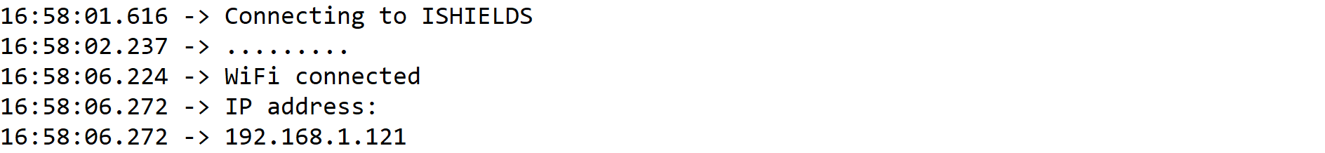
When the connection to the Wi-Fi network is established in the setup() block, the Serial Monitor should display output similar to this (replacing "your-ssid" and the IP address with your actual network name and assigned IP):
During the loop() function, the device sends an HTTP GET request to the specified server. As an example, here’s what you might see in the Serial Monitor when using the sketch:
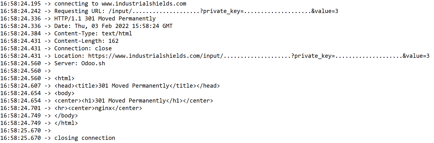
This demonstrates that the ESP32 has successfully communicated with the server and received a response. You can adapt this example to perform additional functions, such as sending sensor data or interacting with other services, by modifying the HTTP request and payload.
Note: Take into account that, if you are using an M-Duino or Ardbox W-Fi & BLE PLC, the Arduino shield and the ESP32 are connected through the Serial1 port of the Arduino <-> Serial2 port of the ESP32. If you want to monitorize this information with the ESP32 you can use the same configuration shown in this post. But, if you want to print the messages on the Serial Port of the M-Duino, you have to configure the code to read the data received through the Serial1 and print it by the Serial. You can find more information about that in this post.
How to connect your ESP32 based PLC to Wi-Fi