
Índice
1. Introducción
2. Requisitos
3. Descripción
4. Implementación
4.1 Configuración del hardware
5. Software
6. Comandos AT
7. Ejecución de un servidor
8. Software
Introducción
En este post se muestra cómo conectar el módulo WiFi ESP8266 a un PLC basado en Arduino.
Requisitos
Ethernet o 20 I/Os PLC: Ethernet PLC 20 I/Os PLC
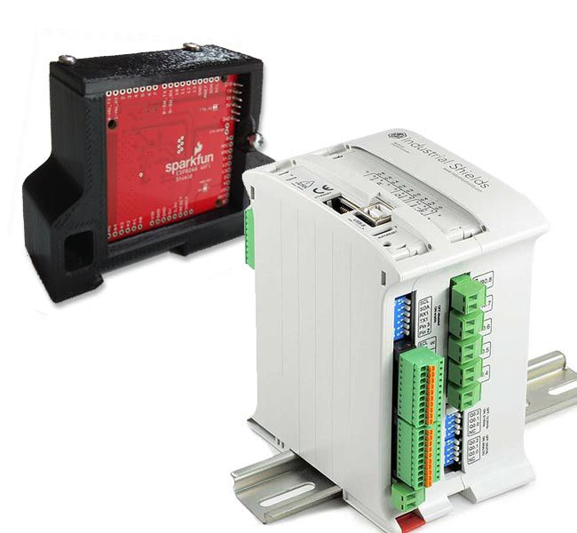
Placas de Industrial Shields: Placas de Industrial Shields
Librería ESP8266 Wifi: Librería ESP8266 Wifi
Descripción
Esta placa WiFi está conectada mediante comunicación serie, por lo que la familia Ethernet PLC es la única en la que se puede conectar este módulo. (En cuanto a la familia 20I/Os no hay comunicación serial libre, ya que están reservadas para los protocolos de comunicación RS-232/RS-485).
El módulo ESP8266 es un sistema en chip WiFi/microcontroller barato y popular. Además, se puede programar como un controlador normal. En realidad, ESP8266 es una puerta de enlace WiFi controlada en serie. Se puede configurar con el comando AT, por lo que utilizando el UART del equipo de Industriales Shields es posible comunicarse con redes WiFi e interactuar con el mundo de IoT a través de protocolos TCP o UDP.
La idea es simple, el ESP8266 está conectado a un PLC Ethernet mediante comunicación serie. La interacción se realiza utilizando comandos AT, por lo que el PLC envía los comandos AT y el mòdulo Wifi los interpreta.
Implementación
- Configuración de hardware
Coloca el selector de interruptores en la posición de serie de hardware (UART HW):
En la tabla siguiente se muestra la conexión de hardware entre ambos dispositivos:
PARA LOS PLCs DE LA FAMILIA M-DUINO:
| Familia M-Duino PLC | ESP8266 Shield |
| TX1 (Serial 1) | RX |
| RX1 (Serial 1) | TX |
| GND | GND |
| 5V | 5V |
PARA LOS PLCs DE LA FAMILIA ARDBOX:
| Familia M-Duino PLC | ESP8266 Shield |
| MISO (pin 14) | RX |
| SCK (pin 15) | TX |
| GND | GND |
| 5V | 5V |
Software
Para trabajar con el ESP8266 Wifi Shield se requiere una biblioteca. Esta biblioteca es compatible con el propietario del Wifi Shield.
PARA LOS PLCs DE LA FAMILIA M-DUINO:
Sigue los siguientes pasos:
2. Abre SparkFunESP8266WiFi.cpp y realiza los siguientes cambios: este sketch se encuentra en:
- C:\Users\{YOUR USER}\Documents\Arduino\libraries\SparkFun_ESP8266_AT_Arduino_Library-master\sr
3. En las primeras líneas en la declaración HARDWARE_SERIAL, cambia las palabras Serial para Serial1. A continuación, se muestra una imagen de donde lo cambia:

PARA LOS PLCs DE LA FAMILIA ARDBOX:
Sigue los siguientes pasos:
1. Descargaa e instala la Librería SparkFun ESP8266 WiFi Shielden Arduino IDE.
2. Abre SparkFunESP8266WiFi.h y realiza los siguientes cambios: este boceto se encuentra en:
- C:\Users\{YOUR USER}\Documents\Arduino\libraries\SparkFun_ESP8266_AT_Arduino_Library-master\srl
3. En las líneas de definición de pasador del croquis (Líneas 33 y 34):
2. Abre SparkFunESP8266WiFi.h y realiza los siguientes cambios: este boceto se encuentra en:
#define ESP8266_SW_RX9
#define ESP8266_SW_TX10
#define ESP8266_SW_TX10
Modifica estas dos líneas por:
#define ESP8266_SW_RX14// ESP8266 UART0 RXI goes to Arduino pin 14
#define ESP8266_SW_TX15// ESP8266 UART0 TXO goes
to Arduino pin 15
#define ESP8266_SW_TX15// ESP8266 UART0 TXO goes
Comandos AT
Una vez que el dispositivo está configurado y la librería está lista, es el momento de fijar el ESP8266. Usando los comandos AT es posible configurar los parámetros ESP8266. A continuación se muestran los parámetros principales, ver más información sobre el siguiente enlace:

Se requiere el codigo adecuado para utilizar los comandos AT y comunicar con ESP8266 a través de Serial1 (RX1, TX1). Con el ejemplo ESP8266_Serial_Passthrough es posible hacerlo. Recuerde seleccionar en el parámetro Monitor serie (Arduino IDE) la velocidad en baudios NL & CR y 9600.
Pruebe los diferentes comandos para comprobar que tiene un buen cableado y código. A continuación, configure la red mediante AT/CWJAP-AT/CWJAP-"APname","APpass".
PARA LOS PLCs DE LA FAMILIA M-DUINO:
#include <SparkFunESP8266WiFi.h>

void setup(){
  Serial.begin(9600);
  esp8266.begin(9600, ESP8266_HARDWARE_SERIAL);  //esp8266 = Serial1 <- Changed previously in the library
}

void loop(){
  serialPassthrough();
}


void serialPassthrough(){
  while (Serial.available())
    esp8266.write(Serial.read());
  while (esp8266.available())
    Serial.write(esp8266.read());
}
PARA LOS PLCs DE LA FAMILIA ARDBOX:
#include <SparkFunESP8266WiFi.h>

void setup()
{
  Serial.begin(9600);
  esp8266.begin (9600, ESP8266_SOFTWARE_SERIAL); //esp8266 = SoftwareSerial (MISO(RX),SCK(TX)) <- Changed previously in the library
}

void loop(){
  serialPassthrough();
}

void serialPassthrough(){
  while (Serial.available())
    esp8266.write(Serial.read());
  while (esp8266.available())
    Serial.write(esp8266.read());
}
void serialPassthrough(){ while (Serial.available()) esp8266.write(Serial.read()); while (esp8266.available()) Serial.write(esp8266.read()); }
Ejecución del servidor
Después de configurar su red con comandos AT, el dispositivo está listo para usarlo con sus opciones completas.
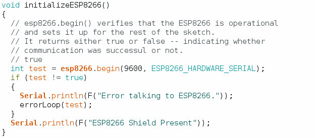
Para verificar su funcionalidad probaremos otro código. En este caso, ejecutaremos el ejemplo ESP8266_Shields_Demo que se puede encontrar en los ejemplos de biblioteca ESP8266 en el Arduino IDE. Antes de subir el código tendremos que hacer un pequeño cambio. En esta función tenemos que añadir 9600 y ESP8266_HARDWARE_SERIAL a nuestra función esp8266.begin(). Echa un vistazo a la siguiente foto:
Después de eso, simplemente selecciona tu unidad de Industriales Shields y el puerto correcto que está conectado. Carga el código y abre el Monitor serie.
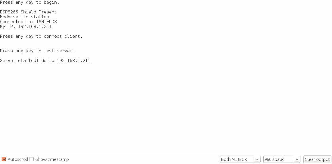
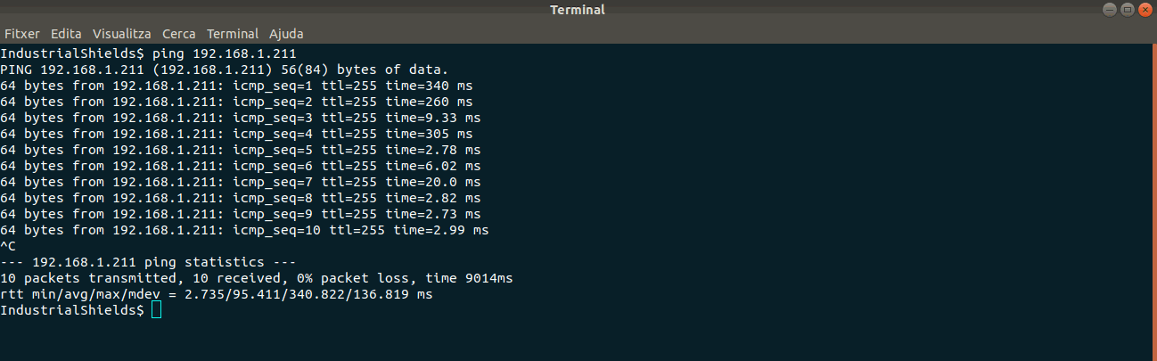
Verás que el programa te pedirá que insertes un carácter aleatorio para hacer un seguimiento del programa. A continuación se muestran dos imágenes y el código.
En la primera imagen se muestra la retroalimentación del Monitor Serie. En el segundo se muestra un ping desde un terminal Linux. Como puedes ver, el módulo Wi-Fi ha inicializado el servidor correctamente.
Software
//////////////////////
// Library Includes //
//////////////////////
// SoftwareSerial is required (even you don't intend on
// using it).
#include <SoftwareSerial.h>
#include <SparkFunESP8266WiFi.h>

//////////////////////////////
// WiFi Network Definitions //
//////////////////////////////
// Replace these two character strings with the name and
// password of your WiFi network.
const char mySSID[] = "ISHIELDS";
const char myPSK[] = "boot2015SHIELDS";

//////////////////////////////
// ESP8266Server definition //
//////////////////////////////
// server object used towards the end of the demo.
// (This is only global because it's called in both setup()
// and loop()).
ESP8266Server server = ESP8266Server(80);

//////////////////
// HTTP Strings //
//////////////////
const char destServer[] = "example.com";
const String htmlHeader = "HTTP/1.1 200 OK\r\n"
                          "Content-Type: text/html\r\n"
                          "Connection: close\r\n\r\n"
                          "<!DOCTYPE HTML>\r\n"
                          "<html>\r\n";

const String httpRequest = "GET / HTTP/1.1\n"
                           "Host: example.com\n"
                           "Connection: close\n\n";

// All functions called from setup() are defined below the
// loop() function. They modularized to make it easier to
// copy/paste into sketches of your own.
void setup()
{
  // Serial Monitor is used to control the demo and view
  // debug information.
  Serial.begin(9600);
  serialTrigger(F("Press any key to begin."));

  // initializeESP8266() verifies communication with the WiFi
  // shield, and sets it up.
  initializeESP8266();

  // connectESP8266() connects to the defined WiFi network.
  connectESP8266();

  // displayConnectInfo prints the Shield's local IP
  // and the network it's connected to.
  displayConnectInfo();

  serialTrigger(F("Press any key to connect client."));
  clientDemo();

  serialTrigger(F("Press any key to test server."));
  serverSetup();
}

void loop()
{
  serverDemo();
}

void initializeESP8266()
{
  // esp8266.begin() verifies that the ESP8266 is operational
  // and sets it up for the rest of the sketch.
  // It returns either true or false -- indicating whether
  // communication was successul or not.
  // true
  int test = esp8266.begin(9600, ESP8266_HARDWARE_SERIAL);
  if (test != true)
  {
    Serial.println(F("Error talking to ESP8266."));
    errorLoop(test);
  }
  Serial.println(F("ESP8266 Shield Present"));
}

void connectESP8266()
{
  // The ESP8266 can be set to one of three modes:
  //  1 - ESP8266_MODE_STA - Station only
  //  2 - ESP8266_MODE_AP - Access point only
  //  3 - ESP8266_MODE_STAAP - Station/AP combo
  // Use esp8266.getMode() to check which mode it's in:
  int retVal = esp8266.getMode();
  if (retVal != ESP8266_MODE_STA)
  { // If it's not in station mode.
    // Use esp8266.setMode([mode]) to set it to a specified
    // mode.
    retVal = esp8266.setMode(ESP8266_MODE_STA);
    if (retVal < 0)
    {
      Serial.println(F("Error setting mode."));
      errorLoop(retVal);
    }
  }
  Serial.println(F("Mode set to station"));

  // esp8266.status() indicates the ESP8266's WiFi connect
  // status.
  // A return value of 1 indicates the device is already
  // connected. 0 indicates disconnected. (Negative values
  // equate to communication errors.)
  retVal = esp8266.status();
  if (retVal <= 0)
  {
    Serial.print(F("Connecting to "));
    Serial.println(mySSID);
    // esp8266.connect([ssid], [psk]) connects the ESP8266
    // to a network.
    // On success the connect function returns a value >0
    // On fail, the function will either return:
    //  -1: TIMEOUT - The library has a set 30s timeout
    //  -3: FAIL - Couldn't connect to network.
    retVal = esp8266.connect(mySSID, myPSK);
    if (retVal < 0)
    {
      Serial.println(F("Error connecting"));
      errorLoop(retVal);
    }
  }
}

void displayConnectInfo()
{
  char connectedSSID[24];
  memset(connectedSSID, 0, 24);
  // esp8266.getAP() can be used to check which AP the
  // ESP8266 is connected to. It returns an error code.
  // The connected AP is returned by reference as a parameter.
  int retVal = esp8266.getAP(connectedSSID);
  if (retVal > 0)
  {
    Serial.print(F("Connected to: "));
    Serial.println(connectedSSID);
  }

  // esp8266.localIP returns an IPAddress variable with the
  // ESP8266's current local IP address.
  IPAddress myIP = esp8266.localIP();
  Serial.print(F("My IP: ")); Serial.println(myIP);
}

void clientDemo()
{
  // To use the ESP8266 as a TCP client, use the
  // ESP8266Client class. First, create an object:
  ESP8266Client client;

  // ESP8266Client connect([server], [port]) is used to
  // connect to a server (const char * or IPAddress) on
  // a specified port.
  // Returns: 1 on success, 2 on already connected,
  // negative on fail (-1=TIMEOUT, -3=FAIL).
  int retVal = client.connect(destServer, 80);
  if (retVal <= 0)
  {
    Serial.println(F("Failed to connect to server."));
    return;
  }

  // print and write can be used to send data to a connected
  // client connection.
  client.print(httpRequest);

  // available() will return the number of characters
  // currently in the receive buffer.
  while (client.available())
    Serial.write(client.read()); // read() gets the FIFO char

  // connected() is a boolean return value - 1 if the
  // connection is active, 0 if it's closed.
  if (client.connected())
    client.stop(); // stop() closes a TCP connection.
}

void serverSetup()
{
  // begin initializes a ESP8266Server object. It will
  // start a server on the port specified in the object's
  // constructor (in global area)
  server.begin();
  Serial.print(F("Server started! Go to "));
  Serial.println(esp8266.localIP());
  Serial.println();
}

void serverDemo()
{
  // available() is an ESP8266Server function which will
  // return an ESP8266Client object for printing and reading.
  // available() has one parameter -- a timeout value. This
  // is the number of milliseconds the function waits,
  // checking for a connection.
  ESP8266Client client = server.available(500);

  if (client)
  {
    Serial.println(F("Client Connected!"));
    // an http request ends with a blank line
    boolean currentLineIsBlank = true;
    while (client.connected())
    {
      if (client.available())
      {
        char c = client.read();
        // if you've gotten to the end of the line (received a newline
        // character) and the line is blank, the http request has ended,
        // so you can send a reply
        if (c == '\n' && currentLineIsBlank)
        {
          Serial.println(F("Sending HTML page"));
          // send a standard http response header:
          client.print(htmlHeader);
          String htmlBody;
          // output the value of each analog input pin
          for (int a = 0; a < 6; a++)
          {
            htmlBody += "A";
            htmlBody += String(a);
            htmlBody += ": ";
            htmlBody += String(analogRead(a));
            htmlBody += "<br>\n";
          }
          htmlBody += "</html>\n";
          client.print(htmlBody);
          break;
        }
        if (c == '\n')
        {
          // you're starting a new line
          currentLineIsBlank = true;
        }
        else if (c != '\r')
        {
          // you've gotten a character on the current line
          currentLineIsBlank = false;
        }
      }
    }
    // give the web browser time to receive the data
    delay(1);

    // close the connection:
    client.stop();
    Serial.println(F("Client disconnected"));
  }

}

// errorLoop prints an error code, then loops forever.
void errorLoop(int error)
{
  Serial.print(F("Error: ")); Serial.println(error);
  Serial.println(F("Looping forever."));
  for (;;)
    ;
}

// serialTrigger prints a message, then waits for something
// to come in from the serial port.
void serialTrigger(String message)
{
  Serial.println();
  Serial.println(message);
  Serial.println();
  while (!Serial.available())
    ;
  while (Serial.available())
    Serial.read();
}