Technical Details
M-DUINO PLC Arduino Ethernet & GPRS 38R I/Os Relay/Analog/Digital PLUS
BACK TO THE PRODUCTInitial Installation
ARDUINO IDE
Arduino IDE is the Original platform to program Arduino boards. This cross-platform application is available on Windows, macOS and Linux and under
the GNU General Public License.
Arduino IDE supports C and C++ code structuring. Industrial Shields recommend using Arduino IDE to program
Arduino Based PLC’s, but any Arduino compatible software are compatible with Industrial Shields Controllers.
Apart from that, Industrial Shields bring the possibility to select your Arduino based PLC into your Arduino IDE and compile your sketches for
the different PLC’s.
Download the Arduino IDE 1.8.6:
POWER SUPPLY
All Arduino based PLC’s can be powered between 12-24V. Both, M-Duino family and Ardbox family, have a consumption between 700mA and 1500mA.
So, the recommended power supply is 2A or higher. Any Industrial power supply will be a good choice to power supply them.
REMEMBER: Out units are designed to be powered between 12-24V. Just powering them with the USB, the unit will not be able to perform their features. USB is
just to program the PLC’s not to power them.
If for some reason you would like to use a power supply lower that 1,5A contact with Industrial Shields technical support to ensure that your system will complete your
functionalities without any power issue.
Next is showed a simple diagram to see how to power supply any Industrial Shields unit.

SWITCH
Our boards have the nomenclature showed below:

The communication board (A zone) is shared with all M-Duino family, for this reason could be that some switches have no functionality or they position is just
unrelated in your unit. In the next table is indicated which switches are related to the unit and their functionality:
A Zone Left Top Switch:

SCL/NC: ALWAYS AT OFF POSITION. On a MDuino 38R Relays/Analog/Digital PLUS this switch is not connected.
SDA/NC: ALWAYS AT OFF POSITION. On a MDuino 38R Relays/Analog/Digital PLUS this switch is not connected.
RX1/I1.1: Choosing between RX1 or the input I1.1. If this switch is ON, it enables the I1.1 input and disables the RX1. If this switch is OFF, it enables RX1 and
disables I1.1.
TX1/I1.0: Choosing between TX1 or the input I1.0. If this switch is ON, it enables the I1.0 input and disables the TX1. If this switch is OFF, it enables TX1 and
disables I1.0.
Pin 3/I0.1: Choosing between Pin 3 or the input I0.1. If this switch is ON, it enables the I0.1 input and disables the Pin 3. If this switch is OFF, it enables Pin 3 and disables I0.1.
GPRS RST /I0.0: ALWAYS AT OFF POSITION. GPRS RST and I0.0 are used by the Sim800L module (The modle/GSM Module).
D53(SD):
ALWAYS AT OFF POSITION.
On a MDuino 38R Relays/Analog/Digital PLUS this switch is
not connected
.
FD RS-485 HD: Choosing between (FD) or (HD). If this switch is ON, it enables the Half Duplex (HD) option and disables the (FD). If this switch is OFF, it enables Full Duplex (FD) and
disables (HD).
A Zone Left Under Switch :

NC: Not connected. This switch is not connected to anything, it doesn’t matter if it is in ON mode or OFF mode.
NC: Not connected. This switch is not connected to anything, it doesn’t matter if it is in ON mode or OFF mode.
RTC (SDA): This switch enables the communication to communicate with the RTC using I2C. Having this switch in ON mode it actives this communication,
whereas if it is in OFF mode it disables the I2C to reach the RTC.
RTC (SCL): This switch enables the communication to communicate with the RTC using I2C. Having this switch in ON mode it actives this communication,
whereas if it is in OFF mode it disables the I2C to reach the RTC.
B Zone Relay:

| SWITCH | ON | OFF |
| 4 | NC | NC |
| 3 | Q0.2 | A0.2 |
| 2 | Q0.1 | A0.1 |
| 1 | Q0.0 | A0.0 |
C Zone Relay

SWITCH
ON
OFF
4
NC
NC
3
Q1.2
A1.2
2
Q1.1
A1.1
1
Q1.0
A1.0
For the Relay Shield if a switch is set to ON, it can only act as Digital Output. If it is set to OFF it can only act as an Analog Output.
tables above.
If it is desired to use an Analog Output the pin must be set to OFF and the pin that will provide this analog output is represented with AX.X, being X any
number of the tables above.
Inputs & Outputs
ANALOG INPUTS
Voltage variation between –Vcc (or GND) and +Vcc, can take any value. An analog input provides a coded measurement in the form of a digital value with an N-bit number. In Digital and Analog I/O there’s self insulation, so its posible to connect them in a different power supply than 24 V.
Inputs:
(8x) Analog (0-10Vdc) /Digital (5-24Vdc) configurable by software.
Know more about Analog Inputs.
TYPICAL CONNECTION

DIGITAL INPUTS
Voltage variation from –Vcc (or GND) to +Vcc, with no intermediate values. Two states: 0 (-Vcc or GND) and 1 (+Vcc). In Digital and Analog I/O there’s self insulation, so its posible to connect them in a different power supply than 24 V.
Digital Inputs provides us PNP input.
Inputs: (3x) Digital Isolated (5-24Vdc) wich can work like interrupt INT (7-24Vdc).
Know more about Digital Inputs.
TYPICAL CONNECTION
- Digital Isolated Input

- Digital No Isolated Input

INTERRUPT INPUTS
Interrupt Service Rutine. A mechanism that allows a function to be associated with the occurance of a particular event. When the event
occurs the processor exits immediately from the normal flow of the program and runs the associated ISR function ignoring any other task.
Inputs: (3x) Interrupt Input (7-24Vdc). “Can work like Digital Input (7-24Vdc)”.
| Interrupt | Arduino Mega Pin | M-Duino Pin |
| INT1 | 3 | I0.1/INT1 |
| INT2 | 19 | I1.1/INT2 |
| INT3 | 18 | I1.0/INT3 |
- I0.1 also as Pin3, enables Interrupts turning ON the switches number 4 of down communication switch.
- I1.0 and I1.1 also as Tx1 and Rx1. Enable Interrupts turning ON the switches number 1 and 2 of up communication switches.
TYPICAL CONNECTION

In this example we activate INT1 using pin I0_1 from M-duino board. When there’s a change
#define INTERRUPT I0_1 //other pins: I0_6, I2_6, I2_5, I1_6, I1_5 (M-Duino) I0_0, I0_3, I0_2, (Ardbox)

volatile bool state = false;

void setup() {
  pinMode(INTERRUPT, INPUT_PULLUP);
  attachInterrupt(digitalPinToInterrupt(INTERRUPT), function_call_back, CHANGE);
}

void loop() {
  if (state == true){
    Serial.println("Interrupt activated");
    state = false;
  }
}

void function_call_back(){ //Change led state
  state = true;
}
ANALOG OUTPUTS
Voltage variation
between
–Vcc (or GND)
and
+Vcc, can take any value. An analog input provides a coded measurement in the form of a digital value with an N-bit number.
In Digital and Analog I/O there’s self insulation, so its posible to connect them in a different power supply than 24 V.
Outputs:
(6x) Analog (0-10Vdc) configurable by switch.
Know more about Analog Outputs.
TYPICAL CONNECTION

DIGITAL OUTPUTS
Voltage variation from –Vcc (or GND) to +Vcc, with no intermediate values. Two states: 0 (-Vcc or GND) and 1 (+Vcc). In Digital and Analog I/O there’s self insulation, so its posible to connect them in a different power supply than 24 V.
Outputs: (6x) Digital Isolated (5-24Vdc) / PWM Isolated
Know more about Digital Outputs.
TYPICAL CONNECTION

RELAYS
A relay is an electromagnetic switch controlled by an electric signal. In Industrial Shields units these devices are already integrated in their boards and can be accessible directly with the function digitalWrite(RX, HIGH). Industrial Shields relays are normally open and can handle a max current of 5A for max voltage 250Vac and 3A for a max DC voltage of 30Vdc.
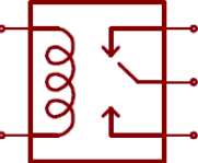
Outputs: (16x) Relay outputs (220Vac – 5A).
Know more about Relay Output.
TYPICAL CONNECTION

PWM OUTPUTS
Pulse Width Modulation. Activate a digital output for a while and keep it off for the rest. The average output voltage, over time, will be equal to the desired analogue value. The frequency between pulse is the same while the pulse width is changed. Attention : A PWM Output gives a
Vcc value during a certain time. So, during a percent time is 5v and the rest of time is 0V. If we supply a device which needs 3v, we can damage it.
| M-Duino Pin | Arduino Mega Pin |
| Q0.2 | 6 |
| Q0.1 | 5 |
| Q0.0 | 4 |
| Q1.2 | 11 |
| Q1.1 | 10 |
| Q1.0 | 8 |
- Q1.0, Q1.1 and Q1.2 Digital/PWM out also as A1.0, A1.1 and A1.2 Analog out.
To use the Digital/PWM configuration pins (QX.X) you have to turn On the switch below:

TYPICAL CONNECTION

Module Pulses from Tools40 library
The Pulses module provides functions for starting and stopping a train of pulses at the desired frequency using PWM pins. The
startPulses(pin, frequency, precision) function starts the train of pulses at the specified frequency and precision. The default frequency is 1kHz and the default precision is 3.The stopPulses(Pin) function stops the train of pulses.pinMode(3, OUTPUT);
startPulses(3, 2000, 3);
stopPulses(3);
IMPORTANT: It is not possible to have different frequencies between the same TIMER Pin’s. Some outputs share the same timer, so they work at the
same frequency.
CAUTION!!! When the TIMER0 pins are used, all the time functions change their functionality as delay(), millis(),micros(),delayMicroseconds() and others.
Next it is showed recommended precision between different frequencies:
| Precision | Frequency Range (Hz) |
| 1 | 30 - 150 |
| 2 | 150 - 500 |
| 3 | 500 - 4k |
| 4 | 4k - 32k |
| 5 | 32k - 4M |
To have a high precision on the desired frequency, it is recommended to use the closer precision to the values of the previous table.
INTERRUPT OUTPUTS
Interrupt Service Rutine. A mechanism that allows a function to be associated with the occurance of a particular event. When the event occurs the processor exits immediately from the normal flow of the program and runs the associated ISR function ignoring any other task.
| Interrupt | Pin Arduino Mega | Pin MDuino |
| INT1 | 3 | I0.1/INT1 |
| INT2 | 18 | I1.0/INT2 |
| INT3 | 19 | I1.1/INT3 |
- I0.1/INT1 also as Pin3 enables Interrupts turning ON the switch number 4 of down communication switch.
- I1.0/INT3 and I1.1/INT2 also as Tx1 and Rx1. Enable Interrupts turning ON the switches number 1 and 2 of up communication switches.
Code example
In this example we activate INT1 using pin I0_6 from M-duino board. When there’s a change
#define INTERRUPT I0_1 //other pins: I2_6, I2_5, I1_6, I1_5 (M-Duino) I0_0, I0_3, I0_2,  (Ardbox)

volatile bool state = false;

void setup() {
  pinMode(INTERRUPT, INPUT_PULLUP);
  attachInterrupt(digitalPinToInterrupt(INTERRUPT), function_call_back, CHANGE);
}

void loop() {
  if (state == true){
    Serial.println("Interrupt activated");
    state = false;
  }
}

void function_call_back(){ //Change led state
  state = true;
}
Communications
Ethernet
Ethernet is the technology that is most commonly used in wired local area networks ( LANs ). A LAN is a network of computers and other electronic devices that covers a small area such as a room, office, or building. It is used in contrast to a wide area network (WAN) , which spans much larger geographical areas. Ethernet is a network protocol that controls how data is transmitted over a LAN. Technically it is referred to as the IEEE 802.3 protocol. The protocol has evolved and improved over time to transfer data at the speed of a gigabit per second.
Our M-Duino family incorporate the integrated W5500 IC.
WX5500
is a Hardwired TCP/IP embedded Ethernet controller that provides easier Internet connection to embedded systems. This chip enables users to have Internet connectivity in their applications by using the single chip in which
TCP/IP
stack, 10/100
Ethernet MAC and PHY are embedded.
The W5500 chip embeds the 32Kb internal memory buffer for the Ethernet packet
processing. With this chip users can implement the Ethernet application by adding the simple socket program.
SPI
is provided for
easy integration with the external microcontroller.
Hardware
Hardware configuration
*IMPORTANT:
Make sure that your Ethernet PLC is powered (12-24Vdc). Just with USB is insufficient power to power up the
Ethernet communication.
Switch configuration
For the Ethernet communication protocol there isn’t
any switch
that
affects
it. So it does not matter the configuration of the
switches to implement Ethernet communication.
Used pins
For Ethernet communication protocol, the defined
Arduino Mega
pin is
pin 10
, which is connected and already internally
assembled to the
WX5500
Ethernet controller. W5500 IC communicates to the Mega board via
SPI bus
already assembled too.
You can
access easily to
Ethernet port
in our Ethernet PLCs, it is located at the top of the communications layer.
Ethernet hardware configuration must be plug and play.
Software
*IMPORTANT: Make sure to download the Arduino based PLC boards for Arduino IDE.
Software Configuration:
Once the hardware configuration is done, it is possible to proceed with the software configuration and also its usage. Firstable it is necessary to include
the Ethernet2.h library provided by Industrial Shields (has the same functionallity as Ethernet.h and also
the same usage).
#include <Ethernet2.h> * Remember that for the V7 version or earlier versions you must use the <Ethernet.h> library.Ethernet2 Library - functions.
* Ethernet2.h library has the same functions as Ethernet.h.
For Ethernet communication there is 3 protocols available:
- Ethernet with HTTP. to know more.
- Ethernet with MQTT, to know more.
- Ethernet with Modbus TCP/IP.
- Master, know more.
- Slave, know more.
Example Codes:
Echo TCP Server:
Once the server is running, any client can connect to the server. On this example it is used an M-Duino to generate the server. The
example of TCP client showed before could be one of the clients.
Next it is showed the Arduino IDE code:
// use Ethernet.h if you have a M-Duino V7 version
#include <Ethernet2.h>
// mac address for M-Duino
byte mac[] = { 0xBE, 0xAD, 0xBE, 0xEF, 0xFE, 0xED };
// Ip address for M-Duino
byte ip[] = { 192, 168, 1, 100 };
int tcp_port = 5566;
EthernetServer server = EthernetServer(5566);
void setup()
{
  // initialize the ethernet device
  Ethernet.begin(mac, ip);
  // start server for listenign for clients
  server.begin();
}
void loop()
{
  // if an incoming client connects, there will be bytes available to read:
  EthernetClient client = server.available();
  if (client.available()) {
    // read bytes from the incoming client and write them back
    // to the same client connected to the server
    client.write(client.read());
  }
}
Echo TCP Client:
Once the server is running, M-Duino can connect to the server. On this example it is used an M-Duino to connect with the Node.js
server called server.js, the same as used on previous example link.
To configure the M-Duino, this post just follows the TCP example from Arduino web site with a few changes. To be able to connect to the server we must know the TCP server IP and the port where this server is listening.
Next it is showed the Arduino code:
#include <Ethernet2.h>
#include <SPI.h>
byte mac[] = { 0xBE, 0xAD, 0xBE, 0xEF, 0xFE, 0xED };
byte ip[] = { 192, 168, 1, 100 };
byte server[] = { 192, 168, 1, 105 }; // Touchberry Pi Server
int tcp_port = 5566;
EthernetClient client;
void setup()
{
  Ethernet.begin(mac, ip);
  Serial.begin(9600);
  delay(1000);
  Serial.println("Connecting...");
  if (client.connect(server, tcp_port)) { // Connection to server.js
    Serial.println("Connected to server.js");
    client.println();
  } else {
    Serial.println("connection failed");
  }
}
void loop()
{
  if (client.available()) {
    if(Serial.available()){
      char s = Serial.read();
      client.write(s); // Send what is reed on serial monitor
      char c = client.read();
      Serial.print(c); // Print on serial monitor the data from server
    }
  }
  if (!client.connected()) {
    Serial.println();
    Serial.println("disconnecting.");
    client.stop();
    for(;;) ;
  }
}
RS-485
RS-485 also known as TIA-485(-A), EIA-485, is a standard defining the electrical characteristics of drivers and receivers for use in serial communications systems. Electrical signaling is balanced, and multipoint systems are supported.
Our Arduino Based PLCs incorporate the integrated circuit MAX485.
MAX485
is a low-power and slew-rate-limited transceiver used for
RS-485 communication
. It works at a single +5V power supply and the rated current is 300 μA. Adopting half-duplex communication to implement the function of converting TTL level into
RS-485 level, it can achieve a maximum transmission rate of 2.5Mbps. MAX485 transceiver draws supply current of between 120μA and 500μA under the unloaded or fully loaded conditions when the driver is disabled.
There is internally installed a
half duplex MAX485
and
MAX485 transmitter
. If you are working on
full duplex
you will use the
MAX485 half duplex to receive data and MAX485 transmitter to send the data.
Hardware
Switch configuration
For the RS-485 communication protocol there is only one switch that affects in this communication. The RS-485 protocol will be
always enabled, the only switch that affects is the one called "FD rs-485 HD". This switch makes the choosing between RS-485 HalfDuplex or RS-485 Full Duplex (RS-422).

| "FD RS-485 HD" (ON Position) | "FD RS-485 HD" (OFF Position) |
| Half Duplex | Full Duplex |
Used pins
For RS-485 communication protocol the defined Arduino Mega pins are showed in the chart below:
| MDuino 38R+ pinout | Arduino Mega pinout |
| DI (Tx) | 14 (Tx Serial3) |
| RO(Rx) | 15 (Rx Serial3) |
| RE (Inverted logic) | 11 |
| DE | 46 |
IMPORTANT:
Make sure to download the
Arduino based PLC boards
for Arduino IDE.
Software Configuration:
Once the hardware configuration is done, it's possible to proceed with the software configuration and also its usage. Firstable it's
necessary to include the RS485.h library provided in our boards.
#include <RS485.h>
To check if the RS-485 port is working it is easy to use the serial monitor from the Arduino IDE using the right sentence inside the
setup() function:
Serial.begin(9600);
Then don’t forget to implement the proper initialization of your communication on the setup() function.
RS485.begin(38400);
NOTE:
Check the velocity of transmission between the PLC and the Laptop and from the PLC to the device connected by RS-485.
Example Codes
Basic RS-485 write example (send):
// Include Industrial Shields libraries
#include <RS485.h>

//// IMPORTANT: check switches configuration

////////////////////////////////////////////////////////////////////////////////////////////////////
void setup() {
  // Begin serial port
  Serial.begin(9600);

  // Begin RS485 port
  RS485.begin(38400);
}

////////////////////////////////////////////////////////////////////////////////////////////////////
void loop() {
  // Wait bytes in the serial port
  if (Serial.available()) {
    byte tx = Serial.read();

    // Echo the byte to the serial port again
    Serial.write(tx);

    // And send it to the RS-485 port
    RS485.write(tx);
  }
}
Basic RS-485 read example (receive):
// Include Industrial Shields libraries
#include <RS485.h>

//// IMPORTANT: check switches configuration

////////////////////////////////////////////////////////////////////////////////////////////////////
void setup() {
  // Begin serial port
  Serial.begin(9600);

  // Begin RS485 port
  RS485.begin(38400);
}
////////////////////////////////////////////////////////////////////////////////////////////////////
void loop() {
  // Print received byte when available
  if (RS485.available()) {
    byte rx = RS485.read();

    // Hexadecimal representation
    Serial.print("HEX: ");
    Serial.print(rx, HEX);

    // Decimal representation
    Serial.print(", DEC: ");
    Serial.println(rx, DEC);
  }
}
Basic RS-485 full-duplex example:
* Remember that to test the full duplex with your Ethernet PLC you must connect the A, B (receivers) to the Y, X(transmitters).
// Include Industrial Shields libraries
#include <RS485.h>
//// IMPORTANT: check switches configuration
//// IMPORTANT: Full duplex mode is only available when device supports it
////////////////////////////////////////////////////////////////////////////////////////////////////
void setup() {
  // Begin serial port
  Serial.begin(9600);
  // Begin RS485 port
  RS485.begin(38400, FULLDUPLEX);
}

////////////////////////////////////////////////////////////////////////////////////////////////////
void loop() {
  // Wait bytes from the RS-485
  if (RS485.available()) {
    byte tx = RS485.read();
    // In full-duplex mode it is possible to send and receive data
    // at the same time in a secure way
    RS485.write(tx);
    // Echo the byte to the serial port
    Serial.write(tx);
  }
}
Important: Using RS-485 we can also implement Modbus RTU see more.
Serial TTL
Communication Interface between two devices with a low level voltage. A Serial port sends data by a bit sequence.
Two signals: Tx (Transmit Data) and Rx (Receive Data).
M-Duino has two TTL ports, RX0/TX0, RX1/TX1. TTL0 is accessed with the function Serial (pins 0 and 1 of the Arduino Mega). TTL1 is accessed with the function Serial1 (pins 18 and 19 of the Arduino Mega)
IMPORTANT: Sim800L library for GPRS use Serial1 to communicate. So, to enable the Serial1 communication connect Pin 2 (RESET GPRS) to HIGH.
Hardware
IMPORTANT: Make sure that your PLC is powered (12-24Vdc).
Switch configuration
To achieve Serial TTL communication there isn't any switch that affects it, it is always enabled. So it does not matter the configuration of the switches to implement Serial TTL communication.
Used pins
| MDuino Ethernet PLC Pinout | Arduino Mega Pinout |
| Tx 0 | 0 |
| Rx 0 | 1 |
| Tx 1 | 18 |
| Rx 1 | 19 |
Software
IMPORTANT: Make sure to download the Arduino based PLC boards for Arduino IDE.
Software Configuration
Once the hardware configuration is done, it's possible to proceed with the software configuration and also its usage. Firstable it's necessary to include the RS232.h library provided in our boards. Then don’t forget to implement the proper initialization of your communication on the setup() function:
Serial.begin(9600);
Basic Serial TTL write example
Reads an analog input on Tx0 (pin 0), prints the result to the serial monitor.
Graphical representation is available using serial plotter (Tools > Serial Plotter menu) on Arduino IDE serial monitor.
// the setup routine runs once when you press reset:
void setup() {
  pinMode(I0_2, INPUT);
  // initialize serial communication at 9600 bits per second:
  Serial.begin(9600);
}
// the loop routine runs over and over again forever:
void loop() {
  // read the input on analog pin 0:
  int sensorValue = analogRead(I0_2);
  // print out the value you read:
  Serial.println(sensorValue);
  delay(1);        // delay in between reads for stability
}
I2C
I2C is a synchronous protocol. Only uses 2 cables, one for the clock (SCL) and one for the data (SDA). This means that the master and the slave send data through the same cable, which is controlled by the master, who creates the clock signal. I2C does not use slave selection, but addressing.
I2C is a serial communications bus. The speed is 100 kbit/s in standard mode, but also allows speeds of 3.4 Mbit/s. It is a bus very used in the industry, mainly to communicate microcontrollers and their peripherals in integrated systems and generalizing more to communicate integrated circuits among themselves that normally reside in a same printed circuit.
Hardware
IMPORTANT: Make sure that your Ethernet PLC is powered (12-24Vdc).
Switch configuration
To achieve I2C communication there isn't any switch that affects it, it is always enabled. So it does not matter the configuration of the switches to implement I2C communication.
Used pins
| MDuino Ethernet PLC Pinout | Arduino Mega Pinout |
| SDA | 20 |
| SCL | 21 |
Software
IMPORTANT: Make sure to download the Arduino based PLC boards for Arduino IDE.
#include <Wire.h>

void setup() {
  Wire.begin(); // join i2c bus (address optional for master)
}

byte x = 0;

void loop() {
  Wire.beginTransmission(8); // transmit to device #8
  Wire.write("x is ");        // sends five bytes
  Wire.write(x);              // sends one byte
  Wire.endTransmission();    // stop transmitting

  x++;
  delay(500);
}
#include <Wire.h>

void setup() {
  Wire.begin(8);                // join i2c bus with address #8
  Wire.onReceive(receiveEvent); // register event
  Serial.begin(9600);           // start serial for output
}

void loop() {
  delay(100);
}

// function that executes whenever data is received from master
// this function is registered as an event, see setup()
void receiveEvent(int howMany) {
  while (1 < Wire.available()) { // loop through all but the last
    char c = Wire.read(); // receive byte as a character
    Serial.print(c);         // print the character
  }
  int x = Wire.read();    // receive byte as an integer
  Serial.println(x);         // print the integer
}
Know more about I2C.
GPRS
General Packet Radio System is a third-generation step toward internet acces. GPRS is also known as GSM-IP that is a Global-System Mobile Communications Internet Protocol as it keeps the users of this system online, allows to make voice calls, and access internet on-the-go. Even Time-Division Multiple Access (TDMA) users benefit from this system as it provides packet radio access.
Hardware
IMPORTANT: Make sure that your Ethernet PLC is powered (12-24Vdc).
Switch configuration
To achieve Serial TTL communication there isn't any switch that affects it, it is always enabled. So it does not matter the configuration of the switches to implement Serial TTL
communication.
Used pins
The SIM800L module is the integrated module for the use of GPRS / GSM in this PLC and to program it you must download this library on your Arduino IDE
When defining the pins in the program, take into account that the internal connections between the Sim800l module and the Arduino Mega are the following:
| Arduino Mega Pinout | Sim800L Pinout |
| 5 Vdc | Vcc |
| GND | GND |
| TX1 (Pin 18) | TXD |
| RX1 (Pin 19) | RXD |
| Pin 2 | RST |
Software
Add the library to enable GPRS communication:
#include <GPRS.h>
Below you can see an example sketch where the PLC acts as a HTTP client, we receive the data that the server in question is sending us and we show them through the serial port.
// GPRS library example
// by Industrial Shields

#include <GPRS.h>

#define PIN "3112"
#define APN "internet"
#define USERNAME ""
#define PASSWORD ""

uint8_t buffer[1024];

////////////////////////////////////////////////////////////////////////////////////////////////////
void setup() {
  Serial.begin(9600UL);

  if (!GPRS.begin(80)) {
    Serial.println("Impossible to begin GPRS");
    while(true);
  }

  int pinRequired = GPRS.isPINRequired();
  if (pinRequired == 1) {
    if (!GPRS.unlockSIM(PIN)) {
      Serial.println("Invalid PIN");
      while (true);
    }
  } else if (pinRequired != 0) {
    Serial.println("Blocked SIM");
    while (true);
  }
}

////////////////////////////////////////////////////////////////////////////////////////////////////
void loop() {
  static uint32_t lastStatusTime = millis();
  if (millis() - lastStatusTime > 2000) {
    GPRSClient client = GPRS.available();
    if (client) {
      size_t len = client.available();
      if (len > 0) {
        client.read(buffer, len);

        Serial.write(buffer, len);
      }
    }
  }
}
SPI
These pins can only work as a 5V pins if the Ethernet protocol is not going to be used. As the Ethernet protocol uses the SPI to communicate with the Arduino board, both behaviours cannot happen at the same time as the Ethernet would not work.
These pins are not stablished with a pull-up or a pull-down configuration. The state of thesepins is unknown. If these pins must be used, they require a pull-up or a pull-downconfiguration. The Arduino board allows the pins to be set in a pull-up configuration. If not itmust be stablished an external pull-up or pull-down circuit in order to correctly work with these pins.
Hardware
IMPORTANT: Make sure that your Ethernet PLC is powered (12-24Vdc).
Switch configuration
To achieve SPI communication there isn't any switch that affects it, it is always enabled. So it does not matter the configuration of the switches to implement SPI communication.
Used pins
For Serial communication protocol the defined Arduino Mega pins are showed in the chart below. For SPI bus MISO, MOSI and CLOCK pins are
common to all the connected devices to the M-Duino, conversely, each of the connected devices will have a single and dedicated SS pin.
| Function | M-Duino connection | Arduino Mega Pinout |
| MISO | SO | 50 |
| MOSI | SI | 51 |
| CLOCK | SCK | 52 |
| RST | Reset | Reset |
IMPORTANT: Make sure to download the Arduino based PLC boards for Arduino IDE.
// inslude the SPI library:
#include <SPI.h>


// set pin 10 as the slave select for the digital pot:
const int slaveSelectPin = 10;

void setup() {
  // set the slaveSelectPin as an output:
  pinMode(slaveSelectPin, OUTPUT);
  // initialize SPI:
  SPI.begin();
}

void loop() {
  // go through the six channels of the digital pot:
  for (int channel = 0; channel < 6; channel++) {
    // change the resistance on this channel from min to max:
    for (int level = 0; level < 255; level++) {
      digitalPotWrite(channel, level);
      delay(10);
    }
    // wait a second at the top:
    delay(100);
    // change the resistance on this channel from max to min:
    for (int level = 0; level < 255; level++) {
      digitalPotWrite(channel, 255 - level);
      delay(10);
    }
  }

}

void digitalPotWrite(int address, int value) {
  // take the SS pin low to select the chip:
  digitalWrite(slaveSelectPin, LOW);
  //  send in the address and value via SPI:
  SPI.transfer(address);
  SPI.transfer(value);
  // take the SS pin high to de-select the chip:
  digitalWrite(slaveSelectPin, HIGH);
}
Know more about SPI.Special Functions
RTC
The term real-time clock is used to avoid confusion with ordinary hardware clocks which are only signals that govern digital electronics, and do not count time in human units. RTC should not be confused with real-time computing, which shares the acronym but does not directly relate to time of day.
Although keeping time can be done without an RTC, using one has benefits:
- Low power consumption (important when running from alternate power
- Frees the main system for time-critical tasks
- Sometimes more accurate than other methods
There is a 3,3V lithium coin cell battery supplying the RTC. M-Duinos RTC Module is based on the DS1307 Chip . The DS1307 serial real-time clock (RTC) is a lowpower, full binary-coded decimal (BCD) clock/calendar plus 56 bytes of NV SRAM. Address and data are transferred serially through an I2C , bidirectional bus. The clock/calendar provides seconds, minutes, hours, day, date, month, and year information. The end of the month date is automatically adjusted for months with fewer than 31 days, including corrections for leap year. The clock operates in either the 24-hour or 12-hour format with AM/PM indicator. The DS1307 has a built-in power-sense circuit that detects power failures and automatically switches to the backup supply. Timekeeping operation continues while the part operates from the backup supply.
Hardware Configuration
IMPORTANT: Make sure that your Ethernet PLC is powered (12-24Vdc) .
Switch configuration
RTC works with the I2C protocol communication, so it is required to have enabled the I2C protocol.
4 switches have to be configured in order to enable the RTC features and I2C communication:
| SWITCH | ON | OFF |
| 4 | NC | NC |
| 3 | NC |
NC |
| 2 | RTC | - |
| 1 | RTC | - |
RTC SCL & RTC SDA must be set to ON mode to enable the I2C wires to the RTC. If they are in OFF mode, the Arduino won’t communicate with the RTC.
Software Configuration
Once the hardware configuration is done, it's possible to proceed with the software configuration and also its usage. Firstable it's necessary to include the RTC.h library provided in our boards (RTC.h includes I2C.h initialitzation, so it will not be necessary to initialize the I2C.h library):
#include <RTC.h>
To check if the RTC port is working it is easy to use the serial monitor from the Arduino IDE using the right sentence inside the setup() function:
#Serial.begin(9600L)
Example Code
Basic RTC Test
// RTC library example
// by Industrial Shields
#include <RTC.h>
////////////////////////////////////////////////////////////////////////////////////////////////////
void setup() {
  Serial.begin(9600L);
}
///////////////////////////////////////////////////////////////////////////////////////////////////
void loop() {
  if (!RTC.read()) {
    Serial.println("Read date error: is time set?");
    }
     else {
    Serial.print("Time: ");
    Serial.print(RTC.getYear());
    Serial.print("-");
    Serial.print(RTC.getMonth());
    Serial.print("-");
    Serial.print(RTC.getMonthDay());
    Serial.print(" ");
    Serial.print(RTC.getHour());
    Serial.print(":");
    Serial.print(RTC.getMinute());
    Serial.print(":");
    Serial.print(RTC.getSecond());
    Serial.print(" (");
    Serial.print(RTC.getTime());
    Serial.println(")");
  }
  delay(1000);
}
uSD
Secure Digital ( SD) is a non-volatile memory card format developed by the SD Card Association (SDA) for use in portable devices.
The newer families of SD card improve card speed by increasing the bus rate (the frequency of the clock signal that strobes information into and out of the card). Whatever the bus rate, the card can signal to the host that it is "busy" until a read or a write operation is complete. Compliance with a higher speed rating is a guarantee that the card limits its use of the "busy" indication. Size: 15 x 11 x 1 mm

IMPORTANT: Make sure that your Ethernet PLC is powered (12-24Vdc).
General Features
The maximum capacity is 4 GB . If a higher capacity is used, it will work correctly but only the first 4GB will work. Allowed file system architectures: FAT32 & FAT16.
The micro SD uses the SPI communication to interact with the Arduino Mega. The SPI protocol is always enabled, as there are no switches that configure it. However there is a switch that must be placed to ON mode in order to communicate with the uSD:
D53(SD) : If this Switch is OFF , it enables the Chip Select of the microSD socket and disables Q2.0 . If this switch is ON, it enables the Q2.0 output, so if the switch is in ON mode the microSD can’t be used .

Using the boards of Industrial Shields , there is a library that simplifies the uSD implementation
called SD . It is the same as the Arduino library, with the only modification of using the pin 53 to select the Chip Select of the uSD chip.
Connections
SD socket Circuit Diagram

| PLC | SD CARD |
| MOSI | MOSI |
| SCK | SCK |
| PIN 53 | CS |
| - | CD |
| MISO | DO |
| - | GND |
Software
Using the boards of Industrial Shields , there is a library that simplifies the uSD implementation called SD . It is the same as the Arduino library, with the only modification of using the pin 53 to select the ChipSelect of the uSD chip .
So, firstable it is necessary to include the SD.h library provided in our boards:
#include <SPI.h>
#include <SD.h>
Sd2Card card;
SdVolume volume;

///////////////////////////////////////////////////////////////////////////////////////////////
void setup() {
  Serial.begin(9600L);
  Serial.println("M-Duino PLUS test started");

// we'll use the initialization code from the utility libraries
// since we're just testing if the card is working!
  if (!card.init(SPI_HALF_SPEED, 53)) {
    Serial.println("initialization failed. Things to check:");
    Serial.println("* is a card inserted?");
    Serial.println("* is your wiring correct?");
    Serial.println("* did you change the chipSelect pin to match your shield or module?");
    return;
  } else {
    Serial.println("Wiring is correct and a card is present.");
  }

  // print the type of card
  Serial.print("\nCard type: ");
  switch (card.type()) {
    case SD_CARD_TYPE_SD1:
      Serial.println("SD1");
      break;
    case SD_CARD_TYPE_SD2:
      Serial.println("SD2");
      break;
    case SD_CARD_TYPE_SDHC:
      Serial.println("SDHC");
      break;
    default:
      Serial.println("Unknown");
  }

  // Now we will try to open the 'volume'/'partition' - it should be FAT16 or FAT32
  if (!volume.init(card)) {
    Serial.println("Could not find FAT16/FAT32 partition.\nMake sure you've formatted the card");
  } else {
    // print the type and size of the first FAT-type volume
    uint32_t volumesize;
    Serial.print("\nVolume type is FAT");
    Serial.println(volume.fatType(), DEC);
    Serial.println();

    volumesize = volume.blocksPerCluster();    // clusters are collections of blocks
    volumesize *= volume.clusterCount();       // we'll have a lot of clusters
    volumesize *= 512;                            // SD card blocks are always 512 bytes
    Serial.print("Volume size (bytes): ");
    Serial.println(volumesize);
    Serial.print("Volume size (Kbytes): ");
    volumesize /= 1024;
    Serial.println(volumesize);
    Serial.print("Volume size (Mbytes): ");
    volumesize /= 1024;
    Serial.println(volumesize);
  }
}

///////////////////////////////////////////////////////////////////////////////////////////////
void loop() {}
For more detailed information about SD class information check the SD library repository.