Programming Arduino on Industrial Environments:
Course 10 Chapters of General Content [IS.AC001.GC]
HANDY MATERIAL TO DEVELOP AN INDUSTRIAL PROJECT USING ARDUINO
I imagine that you already know what Arduino is, so in this course, we will focus on how to use Arduino boards and Arduino based PLCs in industrial environments to execute projects 30% faster.
Using different simple and free tools you will become a high-performance Arduino programmer, capable to develop an Arduino project. The time in an industrial project is money, so we are going to show you save 30% of your time.
- Check and evaluate the different variables and signals connected to the PLC with a graphical interface.
- Use examples already developed, so you don’t have to start from scratch. (Yes, examples! it is not necessary that you write the full code). There are many valuable examples to develop your projects).
- Use libraries for your standard functions.
(Remember: For us, a PLC works like an individual Arduino board. Our PLCs use original Arduino boards inside it, so you can practice the examples showed on this course using original Arduino boards).
Install the following material on your computer to start the chapter #1 next week.
Using a simple graphical platform you can display the PLC status easily and in a friendly way. You can also use it as a SCADA in your project and you can integrate it into your projects as a Human-Machine-Interface. Simple, easy and free. We recommend using an Open Source platform called PROCESSING. (The Arduino IDE is based on this platform, so you will find it very familiar).
Use the original Arduino IDE to program your PLC. Review the different examples from the Arduino IDE and avoid to have to start your project from scratch. It is necessary to select the Arduino board in the right USB port where the Arduino board is connected to the computer.
To configure the different inputs and outputs from the Industrial Shields PLC is easy. You can also use the library from GitHub and forget the pinout checking. See how to upload the library from our blog.
CONNECT AN ARDUINO BOARD TO THE LAPTOP
It is necessary to know 2 essentials things:
Using Processing it is available to have a Graphical Interface done easily and simple which let us monitoring and interact with the PLC and controlling all your installation.
The Arduino IDE let us use libraries where calling our standard algorithms and develop a structured program. We encourage you to see the current version of the original Industrial Shields library from GitHub so you can see how the folders are structured. In the following chapters, we will see how to develop a library and how to call them using the Arduino IDE.
(Remember: Industrial Shields PLCs are working as Original Arduino boards. Our PLCs have original Arduino boards assembled inside. Then, you can practice the course using an Original Arduino board).
Useful Links:
Material to do practices:
- Arduino Leonardo or Arduino Mega (You also can use an Arduino UNO if you get it).
(The devices used with the Arduino Mega and Arduino Leonardo assembled inside have been: From the Ethernet PLCs; the M-duino21. From the 20I/Os PLC; The
INPUTS
It is necessary to know some essentials things:
You can do the course practices using an original Arduino board. In fact, our PLCs have an original Arduino board assembled inside, So, it is not necessary to do practices using our devices if you don’t want. You can use an Arduino Leonardo board, which is the board used in our 20I/Os PLCs (they are called:
Connection Alert:
It is important to note that Arduino works at 5Vdc, then you can not connect industrial sensors directly on an Input on the Arduino board because industrial sensors usually work at 24Vdc. On the other hand, all Arduino based PLCs can be connected to an industrial sensor because all digital inputs can run from 5Vdc to 24Vdc.
(Remember: Industrial Shields PLCs are working as Original Arduino boards. Our PLCs have original Arduino boards assembled inside. Then, you can practice the course using an Original Arduino board)
If you need to connect analog sensors, remember that the analog inputs from the Arduino boards work from 0 to 5Vdc. And you can not connect higher voltages. On the other hand in the industry, it is usually to use analog sensors which work at 4-20mA or 0-10Vdc. Then, convert the current signal to voltage is very easy if you use the Ohm formula: V=IxR, you can see an example of how to convert 4-20mA to 0-10Vdc at our blog.
Useful Links:
Material to do practices:
- Arduino Leonardo or Arduino Mega (You also can use an Arduino UNO if you get it).
(The devices used with the Arduino Mega and Arduino Leonardo assembled inside have been: From the Ethernet PLCs; the M-duino21. From the 20I/Os PLC; The
OUTPUTS
Basic skills:
You can do the course practices using an original Arduino board. In fact, our PLCs have an original Arduino board assembled inside, So, it is not necessary to do practices using our devices if you don’t want. You can use an Arduino Leonardo board, which is the board used in our 20I/Os PLCs (they are called:
Connection Alert:
The outputs from the PLCs provide Voltaje when the state is defined as a HIGH level. Then it is necessary to keep in mind the polarity of the different types of devices connected to the outputs. The voltage provided from the none Optoisolation outputs is the same voltage connected at the PLC as a powering. It means that if the PLC is powered at 12Vcc the outputs work at 12Vcc and 24Vcc if the power supply is 24Vcc. It is also important to join the negative signal as shown on the PLC. To define the level of the outputs it is necessary to use the sentence: DigitaWrite().
(Remember: Industrial Shields PLCs are working as Original Arduino boards. Our PLCs have original Arduino boards assembled inside. Then, you can practice the course using an Original Arduino board)
The analog outputs are programmed exactly as the PWM outputs. Arduino works at 5Vcc but the outputs from the PLC depends on the Voltage connected to the PLC. The Analog outputs work at 0-10Vdc as standardized on the industry. The analog output resolution is 8 bits then you can configure using the sentence AnalogWrite() a value from 0 to 255.
- Useful Links:
Material to do practices:
- Arduino Leonardo or Arduino Mega (You also can use an Arduino UNO if you get it).
(The devices used with the Arduino Mega and Arduino
INPUTS & OUTPUTS. SIMULTANEOUS WORK
You have to know some very basic things:
You can practice with an Arduino board. In the different PLCs we use original Arduino boards, for this
Often, when inputs are read in a PLC, their status is stored in a variable. This variable can be used to send its status through some communication system (RS485, RS232, Ethernet, Serial TTL, etc.) or also to perform a series of functions such as filters, working by flanks, counters, etc. To activate an output it is also common to use a series of variables that will be responsible for defining the state of the output in question.
Work for the student:
In this chapter we are going to make you work. Now you should know how to read a digital input and an analog input. You should also know how to activate a digital output and an analog output. (Remember that the analog outputs are programmed the same as the PWM outputs, although some give you a signal by pulses and the other one gives you an analog signal 0-10Vdc depending on the value that according to the 8bits outputs oscillates between 0-255.
(Remember: For us, a PLC works like an Arduino board. Our PLCs use original Arduino boards so you can try this course using original Arduino boards).
Useful Links:
Material to practice:
-
Arduino Leonardo or Arduino Mega (You can also use an Arduino UNO board if you have one).
(The equipment used with the Arduino Mega and Arduino Leonardo boards inside it were: the Ethernet PLC family, the M-duino21 and the basic 20 I / Os PLCs, the
VARIABLES I
When reading this chapter you have to take into account a series of points:
You can practice with an Arduino board. In the different PLCs we use original Arduino boards, for this
In this chapter, we tell you some basic notions of the types of variables that we treat in a program. This is important since using the variable of the appropriate type in a project is key to avoid possible problems when operating with these. It also allows you to optimize well the code thing that you will appreciate when you go to use different systems of communication with the equipment (RS485, RS232, Ethernet, Serial TTL, etc) Everything that we will see in this chapter serves you so much for the programming in General, not only for Arduino programming but it is very important to know and know that there are differences between the different types of Variables. And also certain similarities between one or the other so you will not have to feel overwhelmed to see this agenda. With the different chapters, you will see and assimilate the use of one type and another.
Review of the agenda:
In this chapter we are going, apart from watching the video, we recommend that you read the different types of variables that we are dealing with.
In the video, we show you where you can see this information so that very quickly you can review the agenda of this chapter. The objective is that you can identify the different types of variables treated as well as have an idea of when to use one type or another.
(Remember: For
Useful Links:
Material to practice:
- Arduino Leonardo or Arduino Mega (You can also use an Arduino UNO board if you have one).
(The equipment used with the Arduino Mega and Arduino Leonardo boards inside it were: the Ethernet PLC family, the M-duino21 and the basic 20 I / Os PLCs, the
VARIABLES II
When reading this chapter you have to take into account a series of points:
You can practice with an Arduino board. In the different PLCs we use original Arduino boards, for this
In this chapter we continue with the types of variables that we treat in a program, where we left it in the previous chapter. This is important since using the variable of the appropriate type in a project is key to avoid possible problems when operating with these. It also allows you to optimize well the code thing that you will appreciate when you go to use different systems of communication with the equipment (RS485, RS232, Ethernet, Serial TTL, etc) Everything what we will see in this chapter serves you so much for the programming in General, not only for Arduino programming but it is very important to know and know that there are differences between the different types of Variables. And also certain similarities between one or the other so you will not have to feel overwhelmed to see this agenda. With the different chapters you will see and assimilate the use of one type and another.
Variables:
It is important to be clear about how different truths are declared and what options we have in each of them. In the final part of the
In the
(Remember: For
Useful Links:
Material to practice:
- Arduino Leonardo or Arduino Mega (You can also use an Arduino UNO board if you have one).
(The equipment used with the Arduino Mega and Arduino Leonardo boards inside it were: the Ethernet PLC family, the M-duino21 and the basic 20 I / Os PLCs, the
COMMUNICATIONS
When reading this chapter you have to take into account a series of points:
You can practice with an Arduino board. In the different
In this chapter, we will explain the different types of basic communications available on an Arduino board, as well as the different industrial adaptations to communicate with industrial equipment. The different types of communication enabled in the Arduino-based PLCs are I2C, Serial TTL, RS232, RS485, and SPI, through which we manage to communicate via Ethernet.
Communications:
It is important to be clear about how each type of communication is connected and what can be done in each of these. How many computers can be connected? If you can make a bus or simply allow 2 teams to communicate with each other. etc.
In the video, we show you differences between the communications by Arduino and in the PLCs based on Arduino that allows connecting directly with other industrial equipment. The objective is that you understand that it is more advisable to use depending on the needs so that in the next chapters we will see more in detail each one of these communication systems.
(Remember: For us, a PLC works like an Arduino board, our PLCs use original Arduino boards so you can try this course using original Arduino boards).
Useful links:
Material to practice:
- Arduino Leonardo or Arduino Mega (You can also use an Arduino UNO board if you have one).
(The equipment used with the Arduino Mega and Arduino Leonardo boards inside it were: the Ethernet PLC family, the M-duino21 and the basic 20 I / Os PLCs, the
ETHERNET
In this chapter we will see how is the communication protocol Ethernet and how it works in general and with our equipment, taking into account the Arduino IDE perspective. We have to remember that any shield with Ethernet port can be programmed using this protocol, in our devices we have a lot with Ethernet connection like the M-Duino family and many others.
Theoretical Introduction
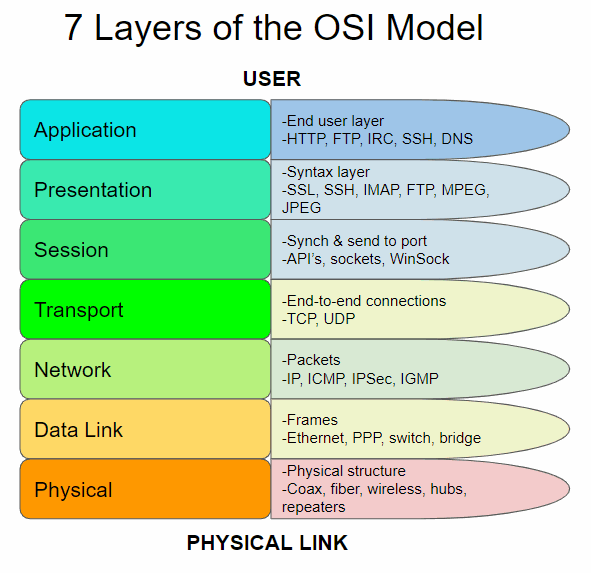
First of all, it is very important to explain the OSI model to understand all the elements which conforms a telecommunication system. The OSI is the Open Systems Interconnection model and this is a conceptual model that characterizes and standardizes the communication functions of a telecommunication or computing system without regard to its underlying internal structure. Its main goal is the interoperability of diverse communication systems with standard communication protocols. This model is divided into seven different abstraction layers.
Every layer serves the layer above it and it is served by the layer below it. For instance, a layer that provides error-free communications across a network provides the path required by applications above it, while it calls the next lower layer to send and receive packets that constitute the contents of that path.
The different layers are:
1.-Application Layer: is the closest to the user, which means both this and the user interact directly with the software application.
2.-Presentation Layer: establishes context between application-layer entities.
3.-Session Layer: controls the connections between computers.
4.-Transport Layer: provides the functional and procedural means of transferring variable-length data sequences from a source to a destination host, while maintaining the quality of service functions.
5.-Network Layer: provides the functional and procedural means of transferring packets from one node to another connected in different networks.
6.-Data Link Layer: provides node-to-node data transfer, a link between two directly connected nodes.
7.-Physical Layer: is responsible for the transmission and reception of unstructured raw data between a device and a physical transmission medium.
Here, we can see an schematic of the layers :
It is important to take into account that there are two types of Modbus; the Modbus TCP that uses Ethernet and is located in layer 7, and the Modbus 232/485 which uses this protocols and is located in all the layers. We have to consider that, many times, the Network, Data and Physical layers are encompassed as media layers and the others as the host layers.
Now that we are located, we can proceed to the main explication on the video and, if you want to discover more information related to Ethernet, you can check the links than below.
Useful Links:
Material to practice:
-
Arduino Leonardo or Arduino Mega (You can also use an Arduino UNO board if you have one).
(The equipment used with the Arduino Mega and Arduino Leonardo boards inside it were: the Ethernet PLC family, the M-duino21 and the basic 20 I / Os PLCs, the Ardbox Relay).